2-
2-6 EDMI Atlas Hardware Reference Manual
Table 2-1 lists the terminal block connections, standard I/O variant.
Terminal Description
TB1
RJ45 connector which is hardware configured
to either RS485 or RS232, or a 5 way terminal
block for RS485.
TB2 Voltage and current inputs.
TB3 I/O - PI5 or PO5.
TB4 I/O - PI6 or PO6.
TB5 I/O - PO1.
TB6 I/O - PO2.
TB7 I/O - PO3.
TB8 I/O - PO4.
• Table 2-1 Terminal block connections
Outputs are BOSFETs, up to 240V, 100mA, AC or DC. Inputs are AC or DC in a
range of voltage options. An active input option is not offered on this variant. All I/O’s
are isolated from each other to 2kV, except for active inputs which share a supply with
the modem port. All I/O are isolated from the line (neutral) and TB1 by 4kV.
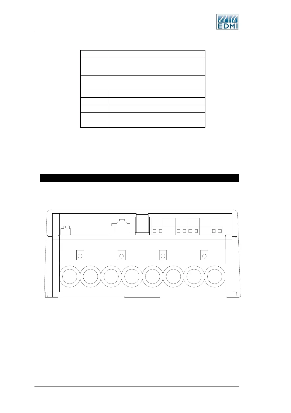
Special I/O Variant
This variant separates the LED’s from the I/O, and provides more I/O type options.
Figure 2-7 shows the terminal layout, and Table 2-2 lists the terminal block connections.
++++
TB3 TB4 TB5 TB6
TB1
Battery
Connector
JP3
TB2
13468101214
25913
• Figure 2-7 Special I/O variant terminal block diagram
 Loading...