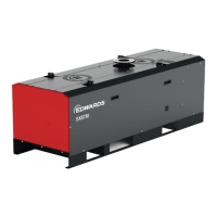
5.2.2 Levelling the pump
The dry pumping s
ystem must be located on a rm, non‐combusble, level surface,
capable of supporng the pump mass, to ensure that it works correctly and is not
damaged. The pump must be level to a maximum of 3 degrees in any direcon,
measured at the pump inlet. It can be located directly on the oor or a frame. Guidance
for the access areas (general and service) is given in the installaon drawings.
▪ Pumps are provided with four oor mounng holes at the boom of the base
frame, refer to Front view on page 10. If necessary, t shims (which must be
supplied) to ensure that the dry pumping system is level.
▪ Pumps with castors can be levelled by adjusng screws the castor has, refer to
Rear view on page 12. Once the dry pumping system has been pushed into the
posion, adjust the levelling castors to make sure that the dry pumping system is
level and is not supported by the castors. Refer to the Installaon drawings on
page 29 for the suggested jacking height.
5.2.3 Securing the pump
To secure the pump in place to prevent inadvertent movement (for example, during an
earthquake), take note of the following:
▪ All dry pumping systems can be secured by ng the bolts or studs (not supplied)
through the mounng holes in the base frame. Use M16 (5/8 inch) bolts with
shake-proof washers or other suitable anchor bolts of the same size.
▪ Ensure that the bolt size and spacing is adequate for the loads ancipat
ed and the
strength of the oor or frame.
▪ To locate the pump directly on the oor, use a concrete foundaon with a mass of
at least 1.5 mes the mass of the pump. Ensure that the length and width of the
foundaon extend at least 100 mm (4 inches) beyond the dimensions of the pump.
▪ If vibraon transmission is a concern, vibraon isolators (not supplied) should be
ed between the base frame and oor mounng bolt or stud.
5.2.4 Piping and venlaon
Piping connecons
The vacuum distribuon and piping system, including the vacuum pump and all related
components must be designed in accordance with generally accepted engineering
pracces. Improperly designed distribuon systems can cause damage to the vacuum
pump. For example, the process inlet pipe must slope away from the vacuum pump.
Process outlet piping, also called exhaust piping, must slope away from the vacuum
pump and must be installed such that it does not create addional back pressure on the
vacuum pump.
It is very important to use adequate pipe diameter for the vacuum network. The
combinaon of restricve pipe diameter and long pipe runs can create a signicant
pressure drop. A rule of thumb on single pump installaons: maintain the diameter of
the pump inlet as far into the process as possible.
Do not install the vacuum pump such that it will cause strain on the inlet or outlet
anges or any connecng pipework.
Refer to Installaon drawings on page 29.
07/2021 - ©Edwards Limited
Page 32A41870880_A
A41870880_A - Installaon
 Loading...