2. Screw the cable gland onto the terminal.
3. Pass the cable through the cable gland. Cables must be with M5 lug to ensure
corr
ect clamping in the main terminal.
4. Fit the earth (ground) wire to the protecve earth connecon.
If further informaon is required about connecng the electrical supply, contact us for
advice.
5.8.2 EMC lter
WARNING: PROTECTIVE EARTH CONNECTION
Risk of injury or damag
e to the equipment. Ground the neutral point on the power
supply to comply with the EMC direcve before turning on the EMC lter.
CAUTION: DRIVE DAMAGE
Risk of drive damag
e. When using a drive with a non‐grounding network, high
resistance grounding or asymmetric grounding network, place the screw for the EMC
lter switch in the OFF posion and disable the built‐in EMC lter. Failure to comply
could cause damage to the drive.
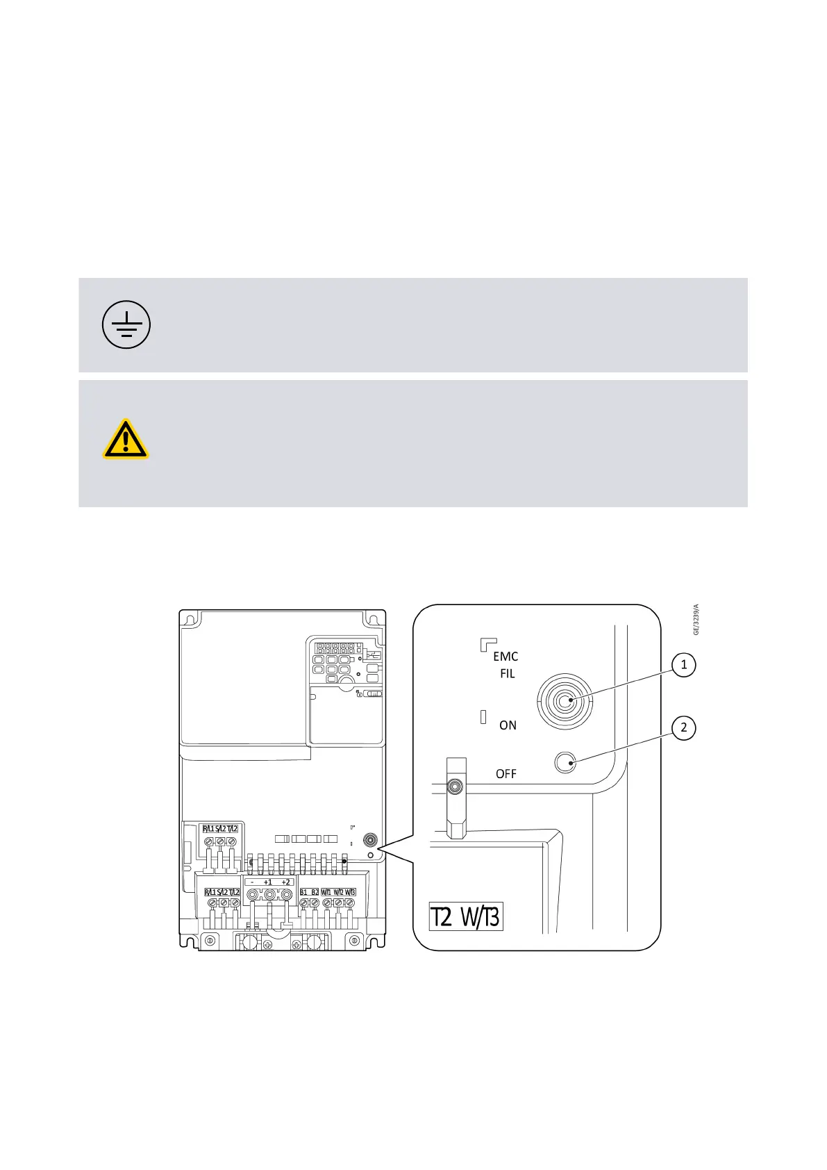
The drive has a built-in EMC lter. The EMC lter switch is in ON posion by default.
Move the screw posion to switch ON (enable) and OFF (disable).
Figure 14 EMC lter switch locaon
1. Switch ON 2. Switch OFF1. Switch ON 2. Switch OFF
07/2021 - ©Edwards Limited
Page 42A41870880_A
A41870880_A - Inst
allaon

 Loading...