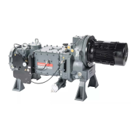
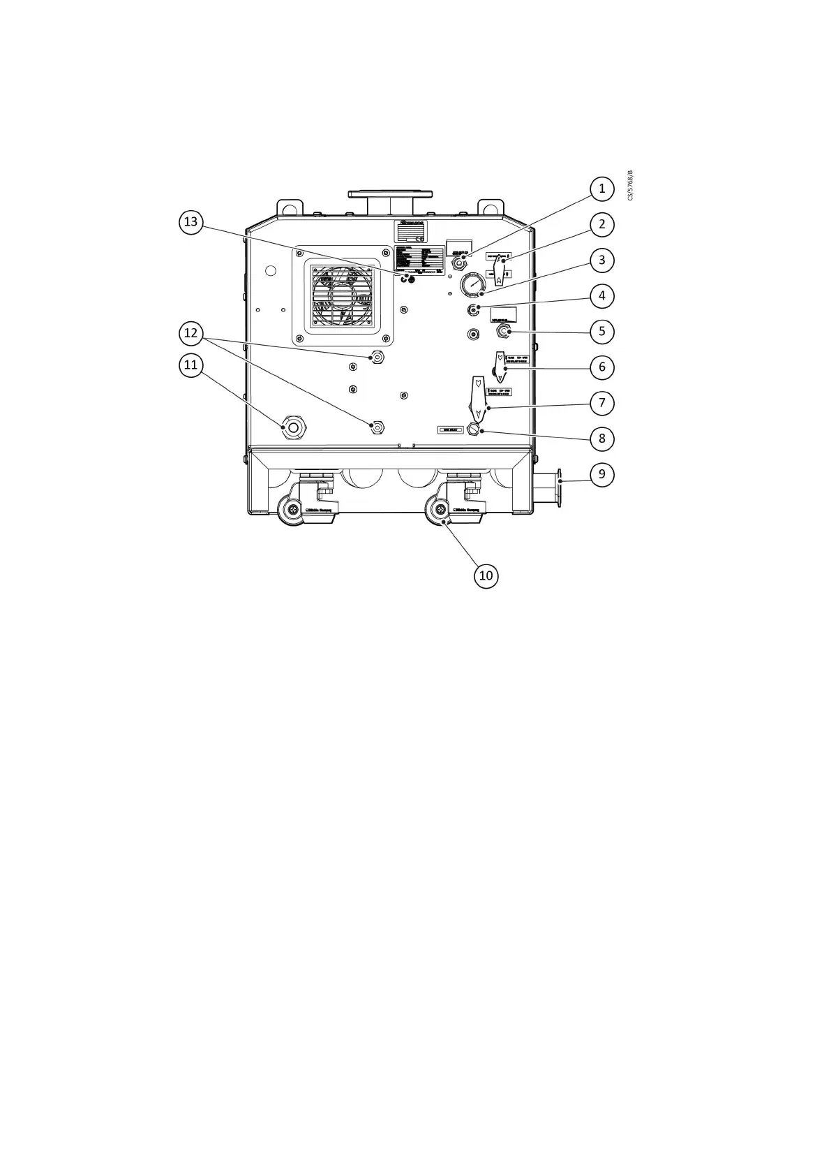
2.4.2 Rear view
Figure 3 Rear view - EXS750
1. Water inlet 2. HV seal purge valve (MV3)
3. Pressure gauge 4. Spare gas port (2 o)
5. W
ater outlet 6. Manual valve gas ballast 0-50 slm (MV1)
7. Manual valve gas ballast 0-80 slm (MV2) 8. Gas inlet port
9. Process outlet 10. Castor (if ed)
11. M40 cable gland 12. M20 cable gland
13. Secondary ground earth stud
1. Water inlet 2. HV seal purge valve (MV3)
3. Pressure gauge 4. Spare gas port (2 o)
5. Water outlet 6. Manual valve gas ballast 0-50 slm (MV1)
7. Manual valve gas ballast 0-80 slm (MV2) 8. Gas inlet port
9. Process outlet 10. Castor (if ed)
11. M40 cable gland 12. M20 cable gland
13. Secondary ground earth stud
07/2021 - ©Edwards Limited
Page 12A41870880_A
A41870880_A - Intr
oducon
 Loading...