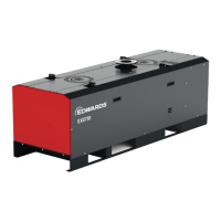
Figure 4 Rear view - EXS450
1. Water inlet 2. HV seal purge valve (MV3)
3. Pressure gauge 4. Spare gas port (2 o)
5. Manual valve gas ballas
t 0-50 slm (MV1) 6. Manual valve gas ballast 0-80 slm (MV2)
7. Water outlet 8. Process outlet
9. Gas inlet port 10. Castor (if ed)
11. M40 cable gland 12. M20 cable gland
13. Secondary ground earth stud
1. Water inlet 2. HV seal purge valve (MV3)
3. Pressure gauge 4. Spare gas port (2 o)
5. Manual valve gas ballast 0-50 slm (MV1) 6. Manual valve gas ballast 0-80 slm (MV2)
7. Water outlet 8. Process outlet
9. Gas inlet port 10. Castor (if ed)
11. M40 cable gland 12. M20 cable gland
13. Secondary ground earth stud
2.4.3 GENIUS Instant Insights (if ed)
Some pumps have a GENIUS BOX mounted in the electrical cabinet. The GENIUS BOX
allows the read-out of parameters of the pump on a user login protected web site
hps://iot.edwardsvacuum.com. The connected antenna is mounted outside the pump.
For more detail, refer to Cloud User Handbook.
07/2021 - ©Edwards Limited
Page 13A41870880_A
A41870880_A - Intr
oducon
 Loading...