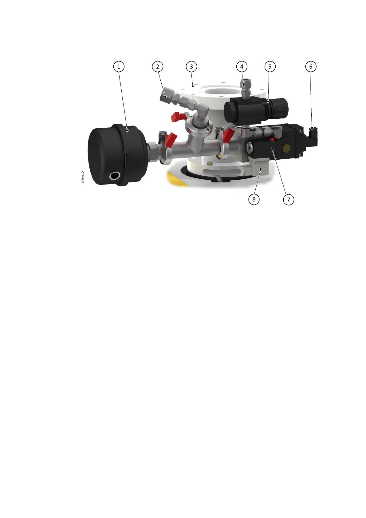
Figure 17 DP clean assembly for the pump only systems
1. Air lter 2. DP clean solven
t ush uid connecon
3. Inlet spool 4. Pneumac valve inlet connecon
5. Pneumac regulator 6. Oponal connecon to the pneumac
valve sensor
7. Pneumac valve 8. Pneumac valve electrical connecon
1. Air lter 2. DP clean solvent ush uid connecon
3. Inlet spool 4. Pneumac valve inlet connecon
5. Pneumac regulator 6. Oponal connecon to the pneumac
valve sensor
7. Pneumac valve 8. Pneumac valve electrical connecon
5.16 Connecng the dry pumping system for serial communicaons
5.16.1 MODBUS
MODBUS-RTU communicaon is available (AC D+ D-). Refer to Figure: Service diagram
for more informaon.
07/2021 - ©Edwards Limited
Page 49A41870880_A
A41870880_A - Inst
allaon
 Loading...