5.4 Electrical connecons
Figur
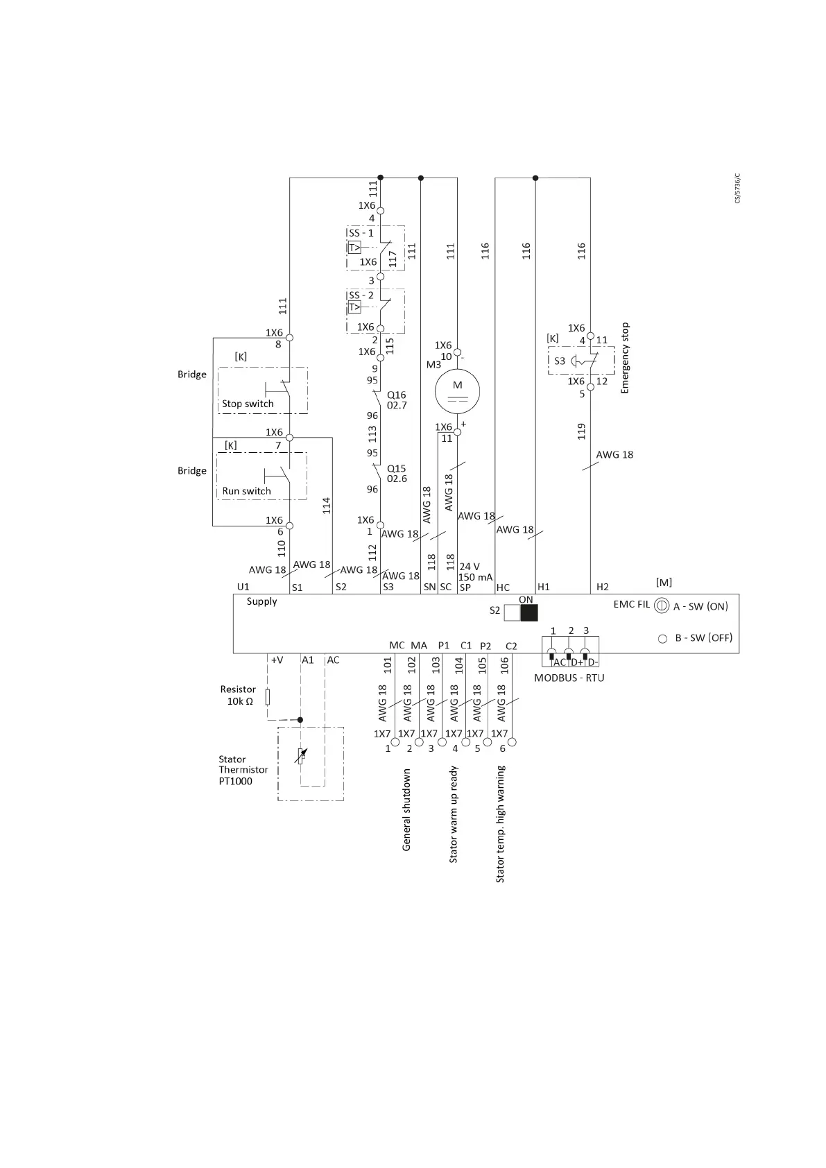
e 11 Service diagram
▪ Installaon of s
t
art switch: Remove the bridge between 1X6:7 and 1X6:8, use a
single core cable (AWG18) to connect 1X6:7 and 1X6:8 with NO (Normally Open)
contact of the start switch.
▪ Installaon of stop switch: Remove the bridge between 1X6:7 and 1X6:6, use single
core cable (AWG18) to connect 1X6:7 and 1X6:6 with NC (Normally Closed) contact
of stop switch.
▪ Installaon of emerg
ency stop switch: Emergency stop switch must be ed
before operang the pump, use single core cable (AWG18) to connect 1X6:4 and
1X6:5 with NC contact of emergency stop switch.
07/2021 - ©Edwards Limited
Page 34A41870880_A
A41870880_A - Inst
allaon

 Loading...