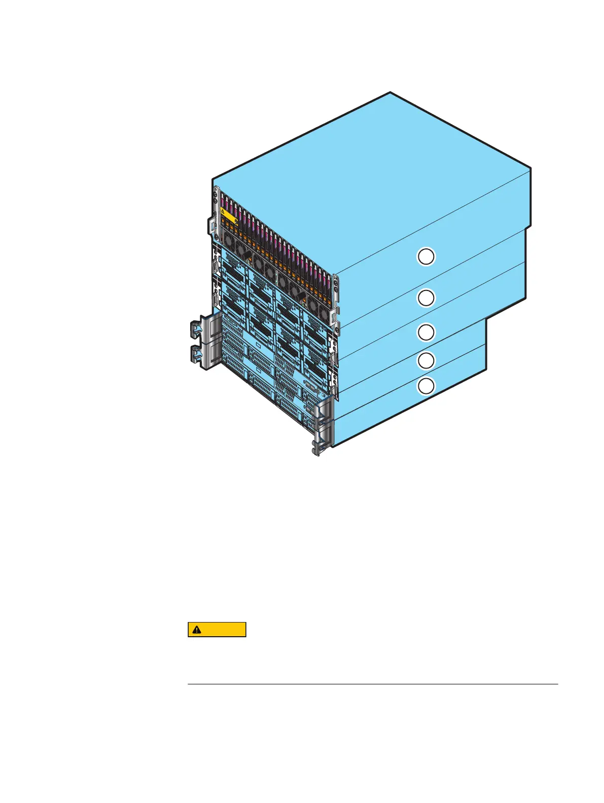
Figure 4 Example of mini-rack components on antistatic floor, mat, or workbench pads
B
A
0
Will Make the Array Unusable
Caution: Array Software on drives 0-3. Removing or relocating them
A
B
SP
SP
B
A
1
2
3
4
5
1: Disk processor enclosure
2: Data Mover enclosure 0
3: Data Mover enclosure 1
4: Control Station 0
5: Control Station 1
6. Unscrew the rear screws and remove the Control Station outer slide rails from the
mini-rack.
7. If any optional blade enclosures are included in the mini-rack, unscrew and remove
their 2U adjustable rails separately.
8.
On the left ganged rail, there is a blue light power connector (see Figure 5 on page
19) protruding from the front which goes through a hole in the front channel of the
mini-rack.
Unscrew the front and rear screws and remove the ganged rails from the mini-rack, out
from the rear, then the front, as shown in Figure 5 on page 19.
Unpack your system
18 EMC VNX Series VNX5600 Unified Installation Guide

 Loading...


