5. (optional) Control Station 1
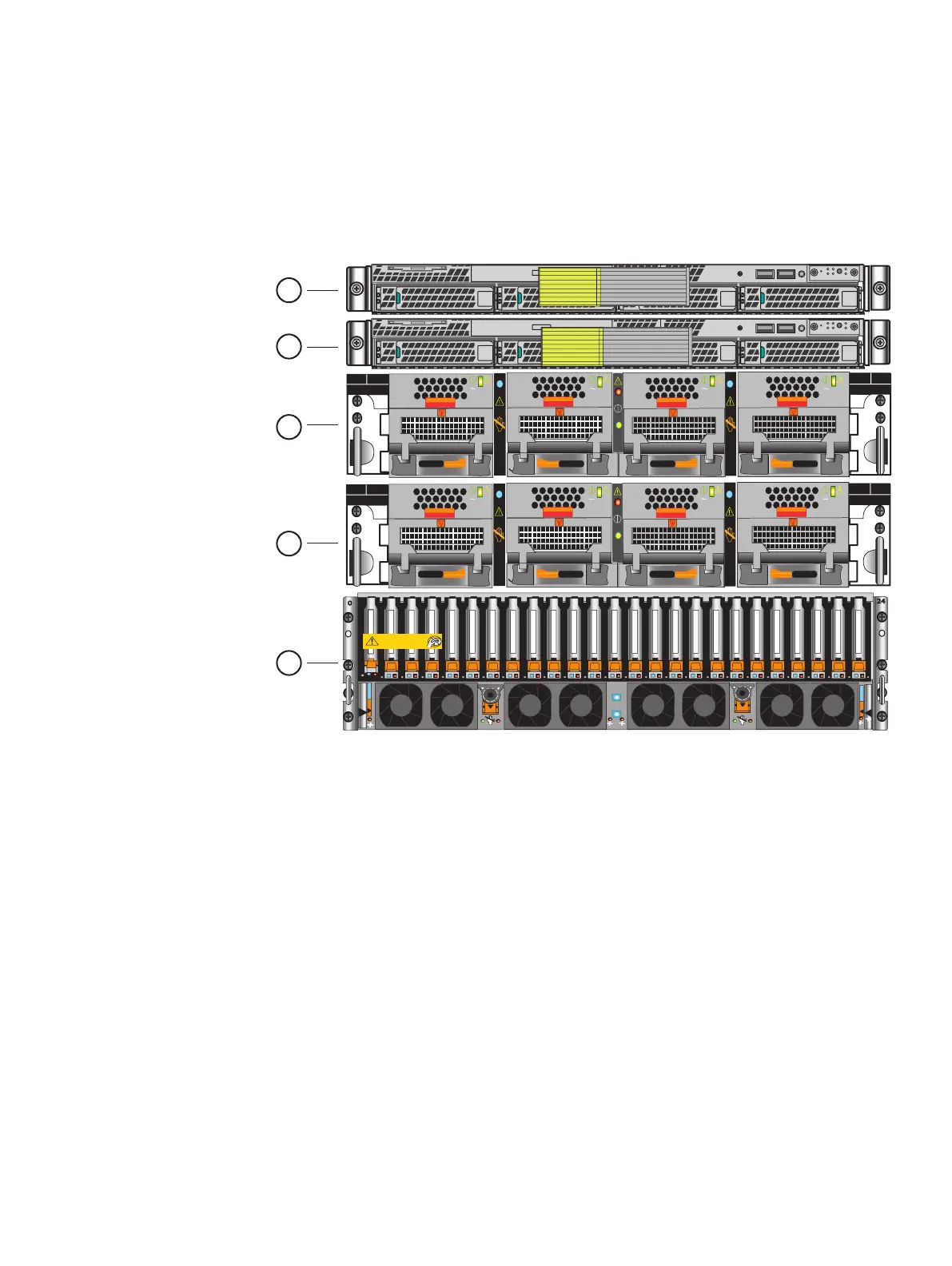
Figure 12 on page 29 shows an example of the front view of the VNX components and
Figure 13 on page 30 shows an example of the rear view of the VNX components.
Your system's hardware information guide provides more detail on each of these
components.
Figure 12 Front view system components
AC
AC
AC
AC
B
PS B0
PS B1
CPU B
PS A0
PS A1
CPU A
A
B
SP
Will Make the Array Unusable
Caution: Array Software on drives 0-3. Removing or relocating them
01
SP
01
AC
AC
AC
AC
B
PS B0
PS B1
CPU B
PS A0
PS A1
CPU A
A
1
2
3
4
5
Assemble components in your cabinet
Installation order of system components 29

 Loading...


