Safety
Information
Product
Information
Mechanical
Installation
Electrical
Installation
Getting
Started
Basic
parameters
Running
the motor
Optimization
SMARTCARD
operation
PC tools
Advanced
parameters
Technical
Data
Diagnostics
UL Listing
Information
194 Affinity User Guide
www.controltechniques.com Issue Number: 5
Solutions Module software
Most Solutions Modules contain software. The software version of the module can be checked by looking at Pr x.02 and Pr x.51.
The software version takes the form of xx.yy.zz, where Pr x.02 displays xx.yy and Pr x.51 displays zz. I.e. for software version 01.01.00, Pr x.02
would display 1.01 and Pr x.51 would display 0
SM-I/O Plus modules do not contain any software, so Pr x.02 and Pr x.51 do not appear.
For further information, refer to the specific Solutions Module User Guide.
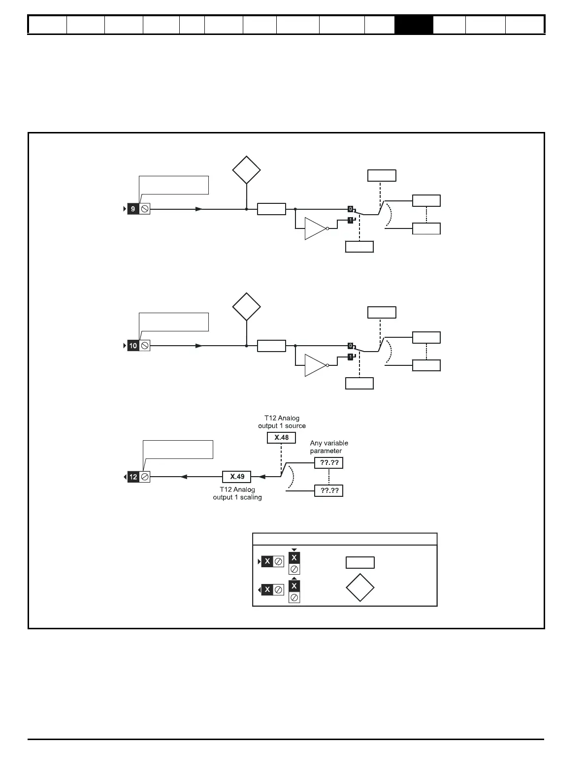
11.14.2 Automation module category
Figure 11-25 SM-I/O Plus analog logic diagram
X.41
T9 Analog
input 1
scaling
input 1 invert
X.40
T9 Analog input 1
(RW)
parameter
Read-only (RO)
parameter
Input
terminals
Output
terminals
The parameters are all shown at their default settings
X.45
X.44
T10 Analog
input 2
invert
T9 Analog
input 1
T10 Analog input 2
T10 Analog
input 2
T10 Analog
input 2
destination
T10 Analog
input 2
scaling
T12 Analog
output 1