Safety
Information
Product
Information
Mechanical
Installation
Electrical
Installation
Getting
Started
Basic
parameters
Running
the motor
Optimization
SMARTCARD
operation
PC tools
Advanced
parameters
Technical
Data
Diagnostics
UL Listing
Information
238 Affinity User Guide
www.controltechniques.com Issue Number: 5
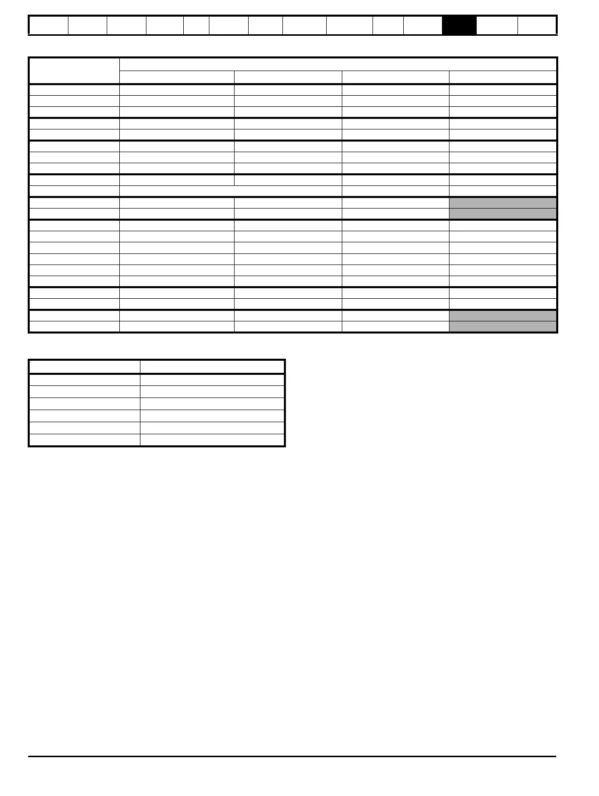
Table 12-14 Losses @ 45°C (113°F) ambient for size 4 to 6 E12/54 drives
Table 12-15 Power losses from the front of the drive when
through-panel mounted
12.1.3 Supply requirements
Voltage:
BAX2XX 200V to 240V ±10%
BAX4XX 380V to 480V ±10%
BAX5XX 500V to 575V ±10%
BAX6XX 500V to 690V ±10%
Number of phases: 3
Maximum supply imbalance: 2% negative phase sequence (equivalent
to 3% voltage imbalance between phases).
Frequency range: 48 to 65 Hz
For UL compliance only, the maximum supply symmetrical fault current
must be limited to 100kA
Size 6 heatsink fan supply requirements
Nominal voltage: 24V
Minimum voltage: 23.5V
Maximum voltage: 27V
Current drawn: 3.3A
Recommended power supply: 24V, 100W, 4.5A
Recommended fuse: 4A fast blow (I
2
t less than 20A
2
s)
12.1.4 Line reactors
Input line reactors reduce the risk of damage to the drive resulting from
poor phase balance or severe disturbances on the supply network.
Where line reactors are to be used, reactance values of approximately
2% are recommended. Higher values may be used if necessary, but may
result in a loss of drive output (reduced torque at high speed) because of
the voltage drop.
For all drive ratings, 2% line reactors permit drives to be used with a
supply unbalance of up to 3.5% negative phase sequence (equivalent to
5% voltage imbalance between phases).
Severe disturbances may be caused by the following factors, for example:
• Power factor correction equipment connected close to the drive.
• Large DC drives having no or inadequate line reactors connected to
the supply.
• Across the line (DOL) started motor(s) connected to the supply such
that when any of these motors are started, the voltage dip exceeds
20%
Such disturbances may cause excessive peak currents to flow in the
input power circuit of the drive. This may cause nuisance tripping, or in
extreme cases, failure of the drive.
Drives of low power rating may also be susceptible to disturbance when
connected to supplies with a high rated capacity.
Line reactors are particularly recommended for use with the following
drive models when one of the above factors exists, or when the supply
capacity exceeds 175kVA:
BA1201 BA1202 BA1203 BA1204
BA1401 BA1402 BA1403 BA1404
Model sizes
BA1405 to BA4606 have an internal DC choke and BA5201
to
BA6602 have internal AC line chokes, so they do not require AC line
reactors except for cases of excessive phase unbalance or extreme
supply conditions.
When required each drive must have its own reactor(s). Three individual
reactors or a single three-phase reactor should be used.
Reactor current ratings
The current rating of the line reactors should be as follows:
Continuous current rating:
Not less than the continuous input current rating of the drive.
Repetitive peak current rating:
Not less than twice the continuous input current rating of the drive.
Model
Drive losses (W) taking into consideration any current derating for the given conditions
3kHz 4kHz 6kHz 8kHz
BA4201-E12/54 430 450 490 530
BA4202-E12/54 520 540 590 640
BA4203-E12/54 610 640 690 750
BA5201-E12/54 1000 1080 1240 1400
BA5202-E12/54 1250 1340 1430 1340
BA4401-E12/54 630 690 810 930
BA4402-E12/54 780 850 1000 1070
BA4403-E12/54 980 1060 1130 1090
BA5401-E12/54 1310 1450 1640 1570
BA5402-E12/54 1680 1550 1520
BA6401-E12/54 2000 2240 2680
BA6402-E12/54 2380 2690 2610
BA4601-E12/54 360 410 520 630
BA4602-E12/54 410 470 590 710
BA4603-E12/54 500 570 710 860
BA4604-E12/54 660 750 940 970
BA4605-E12/54 800 910 990 970
BA4606-E12/54 870 990 1010 980
BA5601-E12/54 1350 1490 1440 1410
BA5602-E12/54 1520 1490 1440 1410
BA6601-E12/54 2130 2480 2400
BA6602-E12/54 2540 2480 2400
Frame size Power loss
1 ≤50W
2 ≤75W
3 ≤100W
4 ≤204W
5 ≤347W
6 ≤480W