Safety
Information
Product
Information
Mechanical
Installation
Electrical
Installation
Getting
Started
Basic
parameters
Running
the motor
Optimization
SMARTCARD
operation
PC tools
Advanced
parameters
Technical
Data
Diagnostics
UL Listing
Information
Affinity User Guide 17
Issue Number: 5 www.controltechniques.com
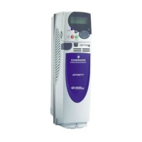
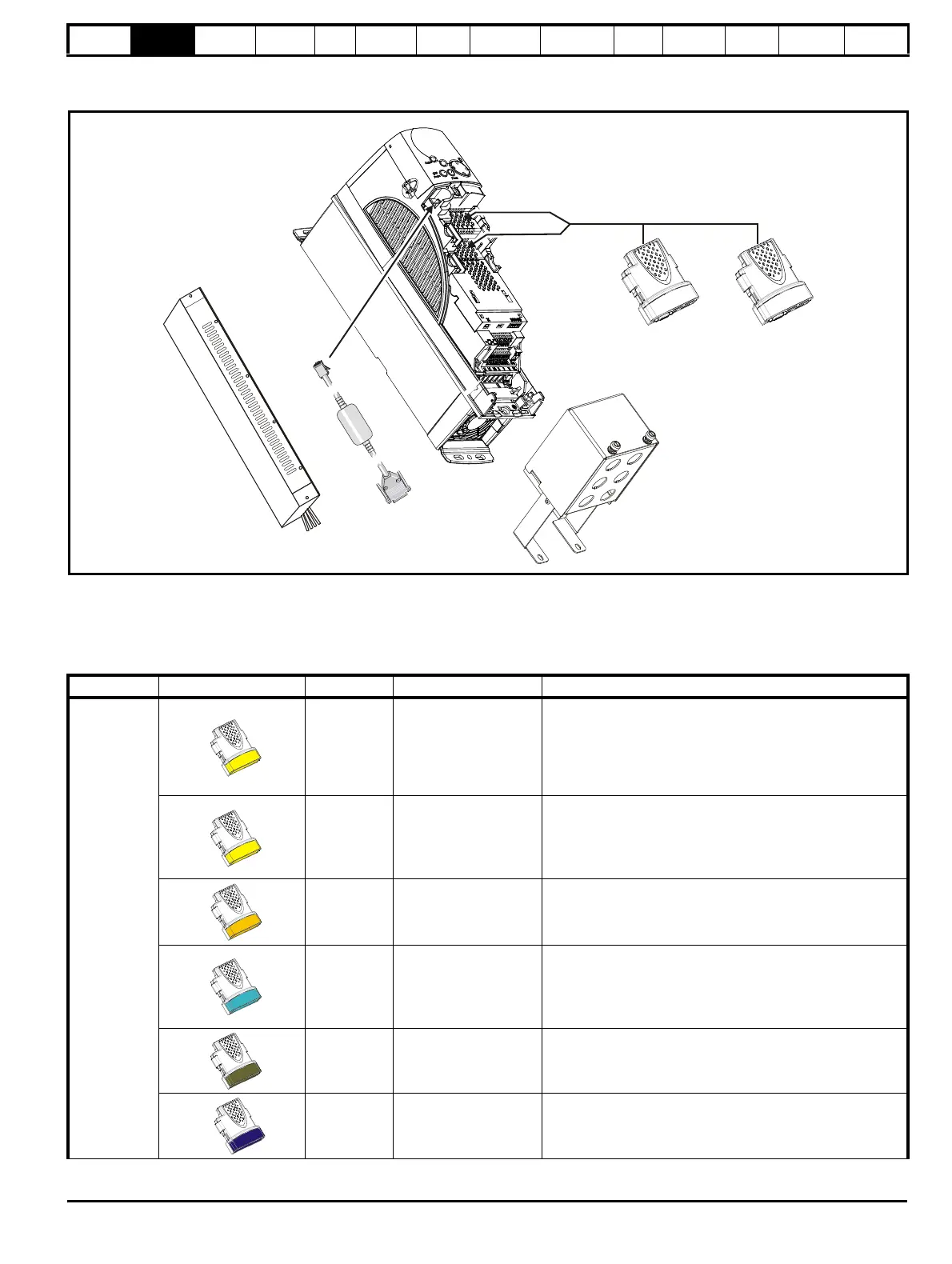
2.8 Options
Figure 2-4 Options available with Affinity
* For sizes 1 and 2 there is only a bottom conduit box available. For sizes 3 to 6 there is a top and bottom conduit box available.
All Solutions Modules are color-coded in order to make identification easy. The following table shows the color-code key and gives further details on
their function.
(Applications)
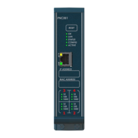
CT Comms
cable
External
footprint /
bookcase
EMC filter
Table 2-6 Solutions Module identification
Type Solutions Module Color Name Further Details
Automation
(I/O
Expansion)
Yellow SM-I/O Plus
Extended I/O interface
Increases the I/O capability by adding the following to the
existing I/O in the drive:
Yellow SM-I/O 32
Extended I/O interface
Increase the I/O capability by adding the following to the
existing I/O in the drive:
• High speed digital I/O x 32
• +24V output
Dark Yellow SM-I/O Lite
Additional I/O
1 x Analog input (± 10V bi-polar or current modes)
1 x Analog output (0-10V or current modes)
3 x Digital input and 1 x Relay
Turquoise SM-I/O PELV
Isolated I/O to NAMUR NE37 specifications
For chemical industry applications
1 x Analog input (current modes)
2 x Analog outputs (current modes)
4 x Digital input / outputs, 1 x Digital input, 2 x Relay outputs
Olive SM-I/O 120V
Additional I/O conforming to IEC 61131-2 120Vac
6 digital inputs and 2 relay outputs rated for 120Vac operation
Cobalt Blue SM-I/O 24V Protected
Additional I/O with overvoltage protection up to 48V
2 x Analog outputs (current modes)
4 x Digital input / outputs, 3 x Digital inputs, 2 x Relay outputs
• Digital inputs x 3
• Analog output (voltage) x 1
• Digital I/O x 3 • Relay x 2
• Analog inputs (voltage) x 2