Safety
Information
Product
Information
Mechanical
Installation
Electrical
Installation
Getting
Started
Basic
parameters
Running
the motor
Optimization
SMARTCARD
operation
PC tools
Advanced
parameters
Technical
Data
Diagnostics
UL Listing
Information
88 Affinity User Guide
www.controltechniques.com Issue Number: 5
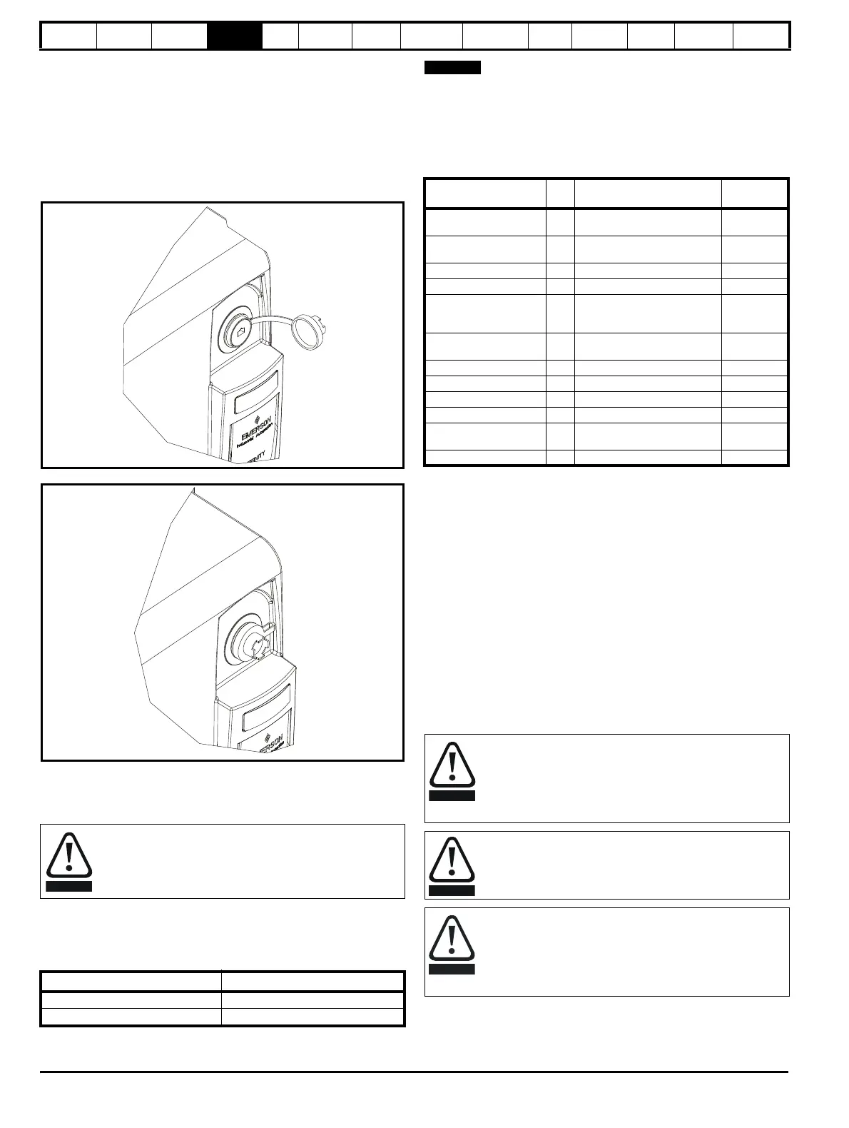
4.12.2 E12/E66 communications connection
The drive serial port is connected to an external RJ 45 connector on the
front of the drive, as shown in Figure 4-36 below.
The serial cable must be a shielded RJ45 cable with an appropriate
connector (suitable for mating with a Bulgin Buccaneer PX0833), rated
to a minimum of IP66.
If a cable is not connected then the connector cap must be installed as
shown in Figure 4-37.
Figure 4-36 Location of RJ45 serial connector
Figure 4-37 Connector with cap installed
4.12.3 Isolation of the communications port
The PC communications port is double insulated and meets the
requirements for SELV in EN 50178:1998.
An isolated serial communications lead has been designed to connect
the drive to IT equipment (such as lap-top computers), and is available
from the supplier of the drive. See below for details:
Table 4-17 Isolated serial comms lead details
The “isolated serial communications” lead has reinforced insulation as
defined in IEC60950 for altitudes up to 3,000m.
N
When using the CT EIA232 Comms cable the available baud rate is
limited to 19.2k baud.
4.13 Terminal connections
4.13.1 General
Table 4-18 The terminal connections consist of:
Key:
All analog terminal functions can be programmed in menu 7.
All digital terminal functions (including the relay) can be programmed in
menu 8.
The setting of Pr 1.14 and Pr 6.04 can cause the function of digital inputs
T25 to T29 to change. For more information, please refer to section
11.21.1 Reference modes on page 215.
In order to meet the requirements for SELV in IEC60950 (IT
equipment) it is necessary for the control computer to be
grounded. Alternatively, when a lap-top or similar device is
used which has no provision for grounding, an isolation
device must be incorporated in the communications lead.
Part number Description
4500-0087 CT EIA232 Comms cable
4500-0096 CT USB Comms cable
Function Qty Control parameters available
Term inal
number
Differential analog input 1
Destination, offset, offset trim,
invert, scaling
5,6
Single ended analog
input
2
Mode, offset, scaling, invert,
destination
7,8
Analog output 2 Source, mode, scaling, 9,10
Digital input 3 Destination, invert, logic select 27, 28, 29
Digital input / output 3
Input / output mode select,
destination / source, invert,
logic select
24, 25, 26
Building automation
network
5 35 to 39
Relay 1 Source, invert 41,42
Drive enable 1 31
+10V User output 1 4
+24V User output 1 Source, invert 22
0V common 6
1, 3, 11, 21,
23, 30
+24V External input 1 2
Destination
parameter:
indicates the parameter which is being controlled by the
terminal / function
Source
parameter:
indicates the parameter being output by the terminal
Mode
parameter:
analog - indicates the mode of operation of the terminal,
i.e. voltage 0-10V, current 4-20mA etc.
digital - indicates the mode of operation of the terminal,
i.e. positive / negative logic (the Drive Enable terminal is
fixed in positive logic), open collector.
The control circuits are isolated from the power circuits in the
drive by basic insulation (single insulation) only. The installer
must ensure that the external control circuits are insulated
from human contact by at least one layer of insulation
(supplementary insulation) rated for use at the AC supply
voltage.
If the control circuits are to be connected to other circuits
classified as Safety Extra Low Voltage (SELV) (e.g. to a
personal computer), an additional isolating barrier must be
included in order to maintain the SELV classification.
If any of the digital inputs or outputs (including the drive
enable input) are connected in parallel with an inductive load
(i.e. contactor or motor brake) then suitable suppression (i.e.
diode or varistor) should be used on the coil of the load. If no
suppression is used then over voltage spikes can cause
damage to the digital inputs and outputs on the drive.