Safety
Information
Product
Information
Mechanical
Installation
Electrical
Installation
Getting
Started
Basic
parameters
Running
the motor
Optimization
SMARTCARD
operation
PC tools
Advanced
parameters
Technical
Data
Diagnostics
UL Listing
Information
Affinity User Guide 41
Issue Number: 5 www.controltechniques.com
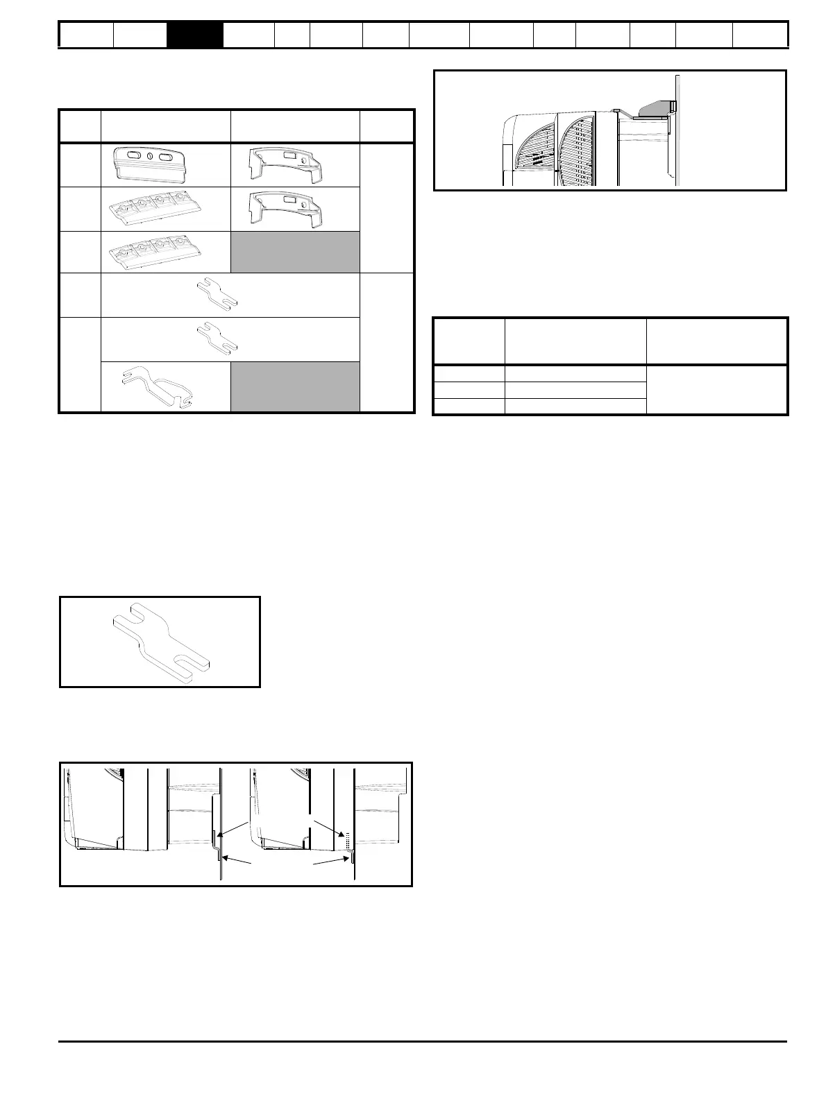
3.5.3 Standard drive surface and through-panel
mounting brackets
Table 3-2 Mounting brackets (Standard)
To avoid damaging the through-panel mounting bracket when through-
panel mounting a size 1 or size 2, the through-panel mounting bracket
should be used to mount the top of the drive to the back plate before the
bottom of the drive is mounted to the back plate. The tightening torque
should be 4 N m (2.9 lb ft).
3.5.4 Installation of the mounting bracket on size 4,
5 and 6
Size 4, 5 and 6 use the same mounting brackets for surface and
through-panel mounting.
The mounting bracket has a long section and a short section.
Figure 3-31 Size 4, 5 and 6 mounting bracket
The mounting bracket must be installed in the correct orientation with the
long section inserted into or attached to the drive and the short section is
attached to the back plate. Figure 3-32 shows the orientation of the
mounting bracket when the drive is surface and through-panel mounted.
Figure 3-32 Orientation of the size 4, 5 and 6 mounting bracket
When through-panel mounted, the mounting brackets on the left hand
side of the drive can be secured using the screws already located there.
On the right hand side, the mounting brackets are just inserted into the
slots in the chassis of the drive; no mounting screws are present here.
Size 5 and 6 also require two top mounting brackets when the drive is
surface mounted. The two brackets should be installed to the top of the
drive as shown in Figure 3-33.
The maximum torque setting for the screws into the drive chassis is
10 N m (7.4 lb ft).
Figure 3-33 Location of top surface mounting brackets for size 5 and 6
3.5.5 E12/E54 drive surface mounting
Table 3-3 states the mounting clearances required when mounting the
E12/54 drive. The drive spacing stated for sizes 4 to 6 are recommended
to allow easy access to the maintainable dust filters. When installing the
drives, access to the filters should not be blocked by cabling or conduit.
For details on how to access the filters please refer to section
3.11.1 E12/E54 filter change on page 64.
Table 3-3 E12/E54 mounting clearances
Model
size
Surface Through-panel
Hole
size
1x2x1
6.5mm
(0.256in)
2x2x1
3x2
4
x4
8.5mm
(0.335in)
5 & 6
x4
x2
Short section
Long section
Short section
Long section
Size
Clearances required at
top and bottom of drive
mm
Clearances required at
side of drive
mm
1 to 3 100
204 150
5 and 6 220