Safety
Information
Introduction Installation
PowerTools
Pro Software
Communications
How
Motion
Works
How I/O
Works
Configuring
an
Application
Programming
Starting and
Stopping
Motion
Starting and
Stopping
Programs
Parameter
Descriptions
Drive
Parameters
Used by
EZMotion
Diagnostics Glossary Index
EZMotion User/Programming Guide 63
Revision A8 www.controltechniques.com
Simulated Encoder Output Parameters
Encoder Simulation Source
The SM-Universal Encoder Plus module has a feature that allows the user to send out a simulated encoder signal for use by
an external device. The Encoder Simulation Source is used to define the source of the encoder signal. By default, the Source
will be configured as the SM-Universal Encoder Plus position (x.05). Any drive parameter in the form of a 0-65535 rollover
counter can be used as the source parameter. Use this field to enter the desired drive source parameter (between 00.00 and
21.51).
By default, EZMotion configures the simulated output to work in Quadrature mode. In order to change the mode, the user will
have to change the Drive Menu Initialization file.
Encoder Simulation Numerator
To add some flexibility to the Simulated Encoder Output signal, the SM-Universal Encoder Plus module allows the user to
scale the output signal by multiplying the source with scaling factor. The scaling factor is made up of a numerator and
denominator allowing the user to achieve nearly any ratio. By default, the Numerator and Denominator are 1.000 implying that
the actual output value is equal to the Source value. Following is an equation that defines the use of the Numerator and
Denominator parameters.
Simulated Encoder Output Signal = Simulated Encoder Source * (Numerator/Denominator)
Encoder Simulation Denominator
To add some flexibility to the Simulated Encoder Output signal, the SM-Universal Encoder Plus module allows the user to
scale the output signal by multiplying the source with scaling factor. The scaling factor is made up of a numerator and
denominator allowing the user to achieve nearly any ratio. By default, the Numerator and Denominator are 1.000 implying that
the actual output value is equal to the Source value. Following is an equation that defines the use of the Numerator and
Denominator parameters.
Simulated Encoder Output Signal = Simulated Encoder Source * (Numerator/Denominator)
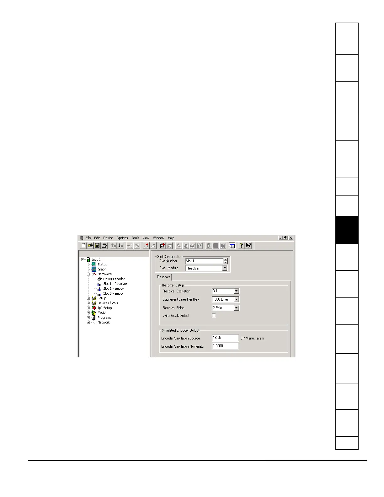
8.3.5 SM-Resolver Module View
Some applications require the use of resolver feedback instead of encoder feedback. In this case, a SM-Resolver module
provides an interface between the resolver and the Unidrive SP/Digitax ST, to be used as position and velocity feedback for
EZMotion. The SM-Resolver also provides a simulated quadrature encoder output that can be sent to another device for
position feedback information.
If Resolver is selected in the Slot# Module list box, the remainder of the view will have configuration parameters to define the
resolver properties. The hierarchy tree automatically updates to show that a SM-Resolver module is populated in that specific
slot, see Figure 68.
Figure 68: Slot # View (SM-Resolver Module)
Following is a description of each of the parameters related to performance and functionality of the SM-Resolver module. For
SM-Resolver module installation instructions, or other SM-Resolver module information, please refer to the SM-Resolver User
Guide.
Resolver Setup Parameters
Resolver Excitation
The Resolver Excitation parameter defines the voltage level of the excitation signal sent out to the resolver hardware. By
entering the turns ratio of the resolver device, the SM-Resolver module will change the excitation signal voltage accordingly.
The resolver manufacturer should specify the turns ratio of the resolver. Supported turns ratios are 3:1 and 2:1.
Equivalent Lines Per Rev
The Equivalent Lines Per Rev parameter is used to define the effective resolution of the resolver in terms of Lines per Rev of
a quadrature encoder. This parameter can be set to 256, 1024, or 4096. The setting of this parameter can limit the maximum