Safety
Information
Introduction
Installation
PowerTools
Pro Software
Communications
How
Motion
Works
How I/O
Works
Configuring
an
Application
Programming
Starting and
Stopping
Motion
Starting and
Stopping
Programs
Parameter
Descriptions
Drive
Parameters
Used by
EZMotion
Diagnostics Glossary Index
EZMotion User/Programming Guide 9
Revision A8 www.controltechniques.com
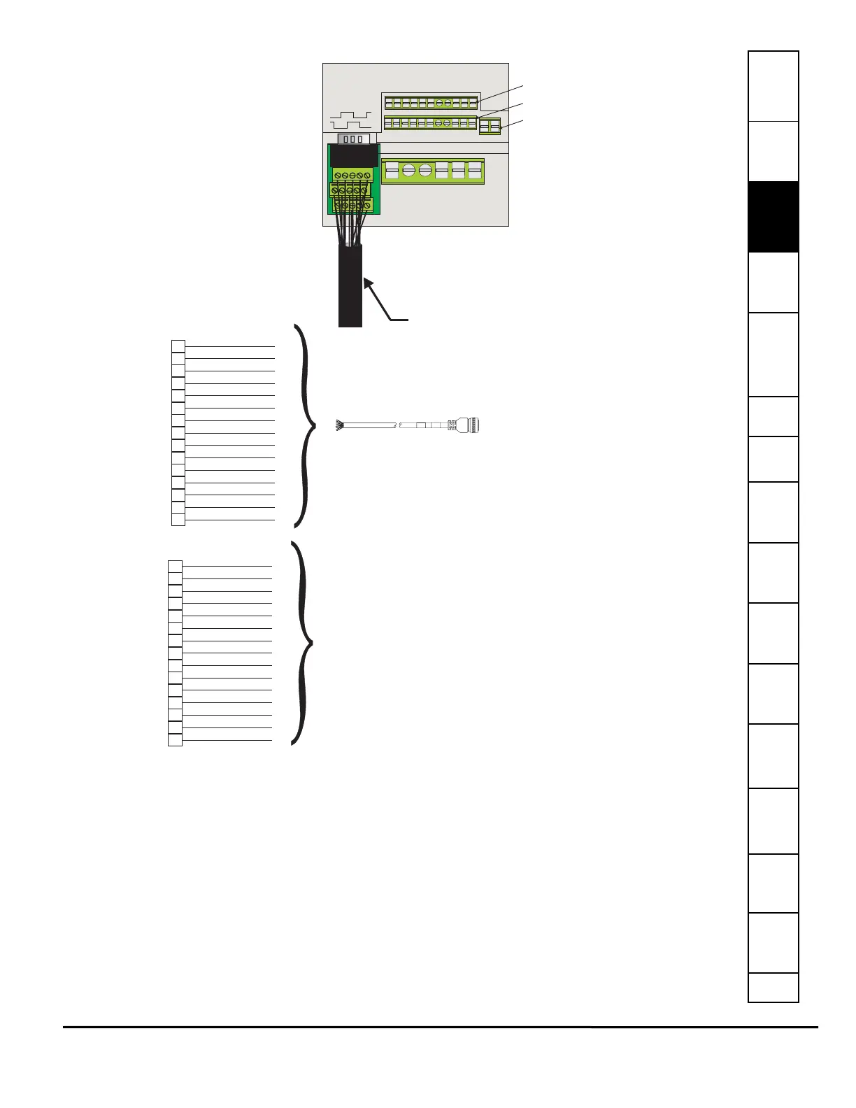
Figure 5: Motor Feedback to Unidrive SP Connection Diagram
3.8 Simple Servo Motor Phasing Test
When connecting a non-standard servo motor to the Unidrive SP, it is necessary to know the wiring configuration of the motor.
At times, all of the necessary wiring documentation for connecting the motor is not readily available from the motor
manufacturer. In that case, it may be possible to follow the simple servo motor phasing test described below. This will help to
determine if the motor phases (U, V, and W) are wired correctly along with the encoder commutation and channel signals. If
the procedure described below is followed, and you still have problems, please refer to the Unidrive SP User Guide for further
wiring information.
Begin by entering the motor peak current, continuous current, number of poles, encoder lines per rev., etc. Then follow the
steps below.
Step 1: Verify wiring of encoder channels per the documentation. Define CW rotation of the motor shaft, from the flange
side, with increasing counts.
I/O Connector 1
I/O Connector 2
I/O Connector 4
UD BV1
Encoder Feedback Cable
Model Number: CFOS-xxx (for NT, MG, or MH Motor)
or SIBAA-xxx (for UM or EZ Motor)
L1 L2 L3 U V W
1
2
3
4
5
6
7
8
9
10
11
12
13
14
15
GREEN
BROWN
BLUE
ORANGE
BLACK
YELLOW
WHT/GRY
GRY/WHT
WHT/BRN
BRN/WHT
RED/ORG
ORG/RED
RED/BLU
BLU/RED
RED/GRN
Encoder Feedback
15 pin D-sub or SM-ETC
CHANNEL A
CHANNEL A/
CHANNEL B
CHANNEL B/
CHANNEL Z
CHANNEL Z/
CHANNEL U
CHANNEL U/
CHANNEL V
CHANNEL V/
CHANNEL W
CHANNEL W/
+5 VDC
0V COMMON
MOTOR THERM
CFOS-xxx Cable
NT, MG, or MH Motor
GRY/PNK
RED/BLU
RED
BLUE
WHT/GRN
BRN/GRN
GREEN
YELLOW
GREY
PINK
BLACK
PURPLE
RED
BLUE
BROWN
1
2
3
4
5
6
7
8
9
10
11
12
13
14
15
Encoder Feedback
15 pin D-sub or SM-ETC
CHANNEL A
CHANNEL A/
CHANNEL B
CHANNEL B/
CHANNEL Z
CHANNEL Z/
CHANNEL U
CHANNEL U/
CHANNEL V
CHANNEL V/
CHANNEL W
CHANNEL W/
+5 VDC
0V COMMON
MOTOR THERM
SIBAA-xxx Cable
EZ or UM Motor