Safety
Information
Introduction Installation
PowerTools
Pro Software
Communications
How
Motion
Works
How I/O
Works
Configuring
an
Application
Programming
Starting and
Stopping
Motion
Starting and
Stopping
Programs
Parameter
Descriptions
Drive
Parameters
Used by
EZMotion
Diagnostics Glossary Index
EZMotion User/Programming Guide 77
Revision A8 www.controltechniques.com
This scaling factor is as follows:
Scaling - Characteristic Distance
This parameter is the distance the load travels (in user units) when the motor travels the characteristic length (in motor
revolutions). This parameter is used along with the DistUnits.CharacteristicLength to establish the relationship between user
distance and actual motor travel distance.
Scaling - Characteristic Length
This parameter is the distance the motor travels (in whole number of revolutions) to achieve one characteristic distance of load
travel. This parameter is used along with the DistUnits.CharacteristicDist to establish the relationship between user distance
and motor travel distance.
Velocity
Time Scale List Box
The time can be one of two values: seconds or minutes. This selection sets the real-time velocity time scale.
Decimal Places
The number of decimal places defined in this parameter determines the max resolution of all real-time velocity parameters
found throughout the PowerTools Pro software. Set between 0 and 6 decimal places. Higher number of decimal places allows
higher velocity resolution, but can limit the max speed allowed by the application.
Acceleration
Time Scale List Box
From this list box, select the acceleration time scale to be used for all real-time profiles. The time scale selected will be used
for both acceleration and deceleration parameters. You can select from milliseconds or seconds.
Decimal Places
The number of decimal places defined in this parameter determines the max resolution of all real-time acceleration and
deceleration parameters found throughout the software. Set between 0 and 6 decimal places.
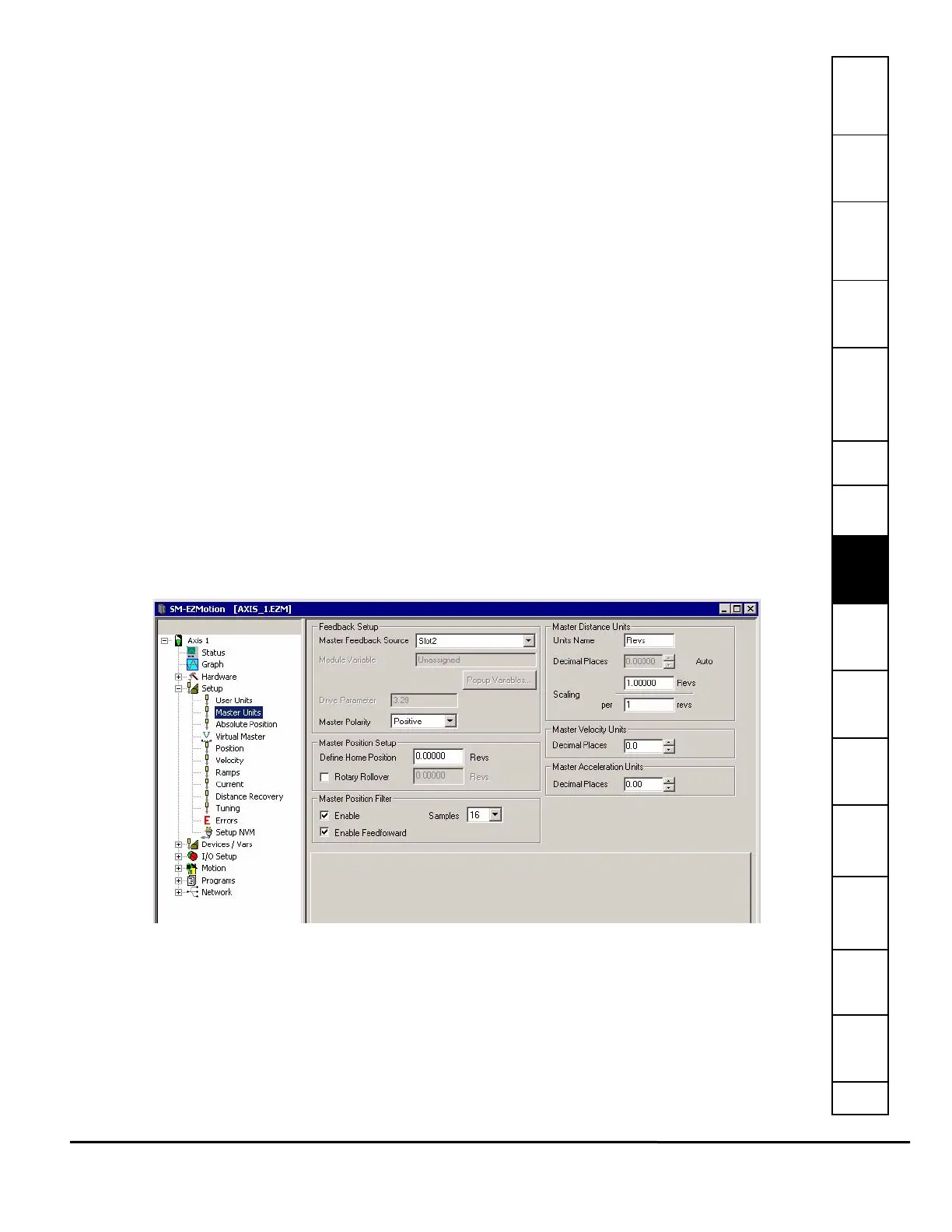
8.4.3 Master Units View
The Master Units view is used to configure the parameters for the master axis used in synchronized motion applications. The
master axis is most often a second encoder, or possibly another upstream drive. Figure 82 shows an example of the Master
Units view.
Feedback Setup
Figure 82: Master Units Setup View
Master Feedback Source
Master Feedback Source indicates the source of the master encoder input. Select from Drive, Slot 1, Slot 2 or Slot 3. If Drive
is selected, then that means that the motor feedback must be routed to one of the option module slots.
Select User Defined Drive Parameter, the Drive Parameter text box will become available to enter the drive parameter that will
be the source of the master.
Select User Defined Module Parameter, the Module Variable text box will become available to enter a parameter. The module
variable can be entered two ways: type the parameter into the text box using the program format for the variable, or click the
Popup Variables button and the Select Variables from Tree window will open. Select the variable and drag it over to the
Module Variable text box.
Scaling
Characteristic Distance
Characteristic Length
------------------------------------------------------------------=