AA
BB
UU
VV
WW
ZZ
1
AA
BB
ZZ
1
E E
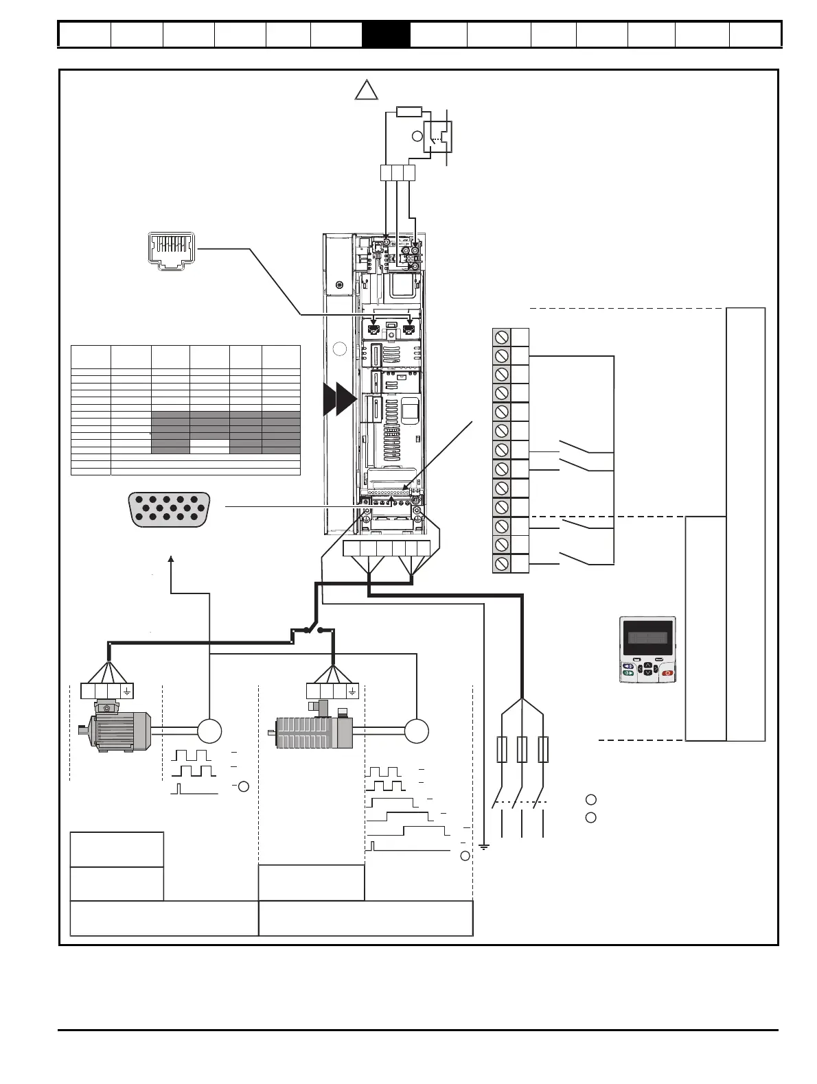
Induction
motor
RFC-S
1
2
Marker pulse optional
Thermal overload for braking resistor
to protect against fire risk. This must be
wired to interrupt the AC supply in the
event of a fault. This is not required if the
optional internal braking resistor is used
T
e
r
m
i
n
a
l
M
o
d
e
K
e
y
p
a
d
M
o
d
e
Communications
port
Keypad
Optional item, must
be installed
for keypad mode
L1 L2 L3
Fuses
L1 L2 L3
U
VW
UVW
Servo motor
(permanent
magnet)
2
!
+
_
BR
Braking resistor
(optional)
Position feedback
connector 15 way D-type
5
10
15
1
6
11
UVW
RFC-A
Open loop
Terminal
AB
AB Servo
SC
Hiperface
SC EnDat
SC SSI
EnDat
BiSS
SSI
Resolver
1 A Cos A (Cos) Data Cos H
2 A\ Cosref A\ (Cos\) Data\ Cos L
3 B Sin B (Sin) CLK Sin H
4 B\ Sinref B\ (Sin\) CLK\ Sin L
5 Z Data Data Freeze Ref H
6 Z\ Data\ Data\ Freeze Ref L
7U
8U\
9V
10 V\
11 W CLK
12 W\ CLK\
13 + V
14 0 V
15 Thermistor Input
3
4
RUN FWD
RUN REV
10
11
8
9
6
7
4
5
3
24V
2
1
SAFE TORQUE
OFF 1
12
13
SAFE TORQUE
OFF 2
RFC-A
Sensorless
RFC-S
Sensorless

 Loading...


