Safety
information
Product
information
Mechanical
installation
Electrical
installation
Getting
started
Basic
parameters
Running
the motor
Optimization
NV Media Card
Operation
Onboard
PLC
Advanced
parameters
Technical
data
Diagnostics
UL listing
information
40 Unidrive M702 User Guide
Issue Number: 3
Example
To calculate the size of an enclosure for the following:
• Three drives operating at the Normal Duty rating
• External EMC filter for each drive
• Braking resistors are to be mounted outside the enclosure
• Maximum ambient temperature inside the enclosure: 40 °C
• Maximum ambient temperature outside the enclosure: 30 °C
For example, dissipation of each drive: 101 W and dissipation of each
external EMC filter: 6.9 W (max).
Total dissipation: 3 x (101 + 6.9) = 323.7 W
Insert the following values:
T
int
40 °C
T
ext
30 °C
k 1.3
P 323.7 W
Then:
= 126.2 m
3
/hr (74.5 ft
3
/min) (1 m
3
/ hr = 0.59 ft
3
/min)
3.7 Enclosure design and drive ambient
temperature
Drive derating is required for operation in high ambient temperatures
Totally enclosing or through panel mounting the drive in either a sealed
cabinet (no airflow) or in a well ventilated cabinet makes a significant
difference on drive cooling.
The chosen method affects the ambient temperature value (T
rate
) which
should be used for any necessary derating to ensure sufficient cooling
for the whole of the drive.
The ambient temperature for the four different combinations is defined
below:
1. Totally enclosed with no air flow (<2 m/s) over the drive
T
rate
= T
int
+ 5 °C
2. Totally enclosed with air flow (>2 m/s) over the drive
T
rate
= T
int
3. Through panel mounted with no airflow (<2 m/s) over the drive
T
rate
= the greater of T
ext
+5 °C, or T
int
4. Through panel mounted with air flow (>2 m/s) over the drive
T
rate
= the greater of T
ext
or T
int
Where:
T
ext
= Temperature outside the cabinet
T
int
= Temperature inside the cabinet
T
rate
= Temperature used to select current rating from tables in
Chapter 12 Technical data on page 227.
3.8 Heatsink fan operation
The drive is ventilated by an internal heatsink mounted fan. The fan
housing forms a baffle plate, channelling the air through the heatsink
chamber. Thus, regardless of mounting method (surface mounting or
through-panel mounting), the installing of additional baffle plates is not
required.
Ensure the minimum clearances around the drive are maintained to
allow air to flow freely.
The heatsink fan on all sizes is a variable speed fan. The drive controls
the speed at which the fan runs based on the temperature of the
heatsink and the drive's thermal model system. The maximum speed at
which the fan operates can be limited in Pr 06.045. This could incur an
output current derating. Refer to section 3.13.2 Fan removal
procedure on page 50 for information on fan removal. The size 6
onwards is also installed with a variable speed fan to ventilate the
capacitor bank.
3.9 Enclosing standard drive for high
environmental protection
An explanation of environmental protection rating is provided in section
12.1.9 IP / UL Rating .
The standard drive is rated to IP20 pollution degree 2 (dry, non-
conductive contamination only) (NEMA 1). However, it is possible to
configure the drive to achieve IP65 rating (NEMA 12) at the rear of the
heatsink for through-panel mounting (some current derating is required).
Refer to Table 12-2 on page 229.
This allows the front of the drive, along with various switchgear, to be
housed in an IP65 (NEMA 12) enclosure with the heatsink protruding
through the panel to the external environment. Thus, the majority of the
heat generated by the drive is dissipated outside the enclosure
maintaining a reduced temperature inside the enclosure. This also relies
on a good seal being made between the heatsink and the rear of the
enclosure using the gaskets provided.
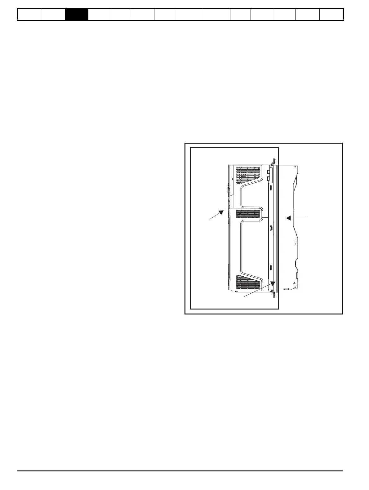
Figure 3-30 Example of IP65 (NEMA 12) through-panel layout
The main gasket should be installed as shown in Figure 3-31.
On drive sizes 3, 4 and 5, in order to achieve the high IP rating at the
rear of the heatsink it is necessary to seal a heatsink vent by installing
the high IP insert as shown in Figure 3-33, Figure 3-34 and Figure 3-35.
V
31.3× 323.7×
40 30–
---------------------------------------
=
IP20
(NEMA1)
IP65 (NEMA 12)
enclosure
Drive with
high IP insert
installed
Gasket
seal

 Loading...


