Electrical connection Liquiline System CA80SI
30 Endress+Hauser
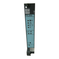
1 Indicator LEDs 6 Slot for display cable
1)
2 Voltage connection
1)
7 Service interface
1)
3 Alarm relay connection 8 Connections for 2 Memosens sensors (optional)
4 Power supply for digital fixed cable
sensors with Memosens protocol
9 Current outputs
5 SD card slot
1) Internal device connection. Do not disconnect the plug.
85
85
86
86
41
43
42
87
88
97
98
31
31
32
32
SD
Display
1
2
Sensor
0/4 ... 20 mA
Sensor supply
+
+
–
+
+
–
1
2
Service
PK
GY
PK
GYGY
1
2
–
BN
WH
GN
YE
BN
WH
GN
YE
87
88
97
98
+
–
A
B
+
–
A
B
–
Alarm
HART
Power
(internal)
24VDC
24V
12,5V
3,3V
A0016537
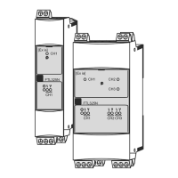
30 Base module E wiring diagram
7.3.2 Connecting the sensors
Only use terminated original cables where possible.
GN/YE
YE
GN
BN
WH
GND
+
–
Com A
Com B
GY
A0024019
31 Example of a Memosens CYK10 data cable
Connecting the ferrules of the sensor cable to the base module E
1. To access the electronics compartment, proceed as described in the "Routing the
cables" section .
2. Guide the sensor connecting cable from below through the cable gland on the inner
rear panel of the device and feed it up into the electronics compartment.
3. Establish the connection as per → 31, 30.

 Loading...