Do you have a question about the Epson EMP-TW1000 and is the answer not in the manual?
Defines procedures that could cause personal injury if not strictly observed.
Defines precautions that could cause equipment damage if ignored.
Covers safety measures to protect operators from electrical shock and physical injury.
Outlines procedures to keep the projector in good working order and prevent damage.
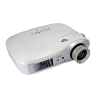
Overview of the projector's capabilities and target market.
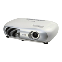
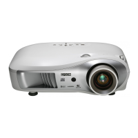
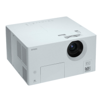
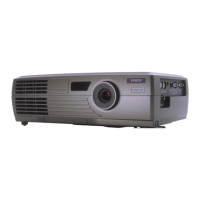
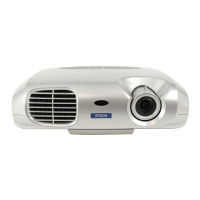
Identifies external components of the projector.
Illustrates the main internal parts of the projector.
Details the functions of each button on the projector's remote control.
Lists detailed technical specifications for the projector's parts and performance.
Outlines the specifications for various input/output interfaces.
Displays dimensional drawings of the projector.
Shows external dimensions of the projector in inches.
Illustrates and names external parts like control panel, vents, lens adjustments, feet, and ports.
Introduces the main hardware components and their functions.
Illustrates the circuit connections between major components and the MA board.
Presents a block diagram of the projector's control circuits.
Describes the components and technology of the optical engine.
Explains the lamp unit, its life, and the need for lamp timer resets.
Describes the function and components of the main control board.
Describes the power supply unit and its functions.
Explains the function of the ballast unit in powering the lamp.
Details the sensors and switches used for temperature monitoring.
Identifies the locations of the four cooling fans in the projector.
Explains the meaning of the operation and warning LEDs.
Details advantages of the D6 series light valves, including improved writing and low power.
Lists sensors like lamp lid detection, safety switch, and thermistors.
Provides a flowchart for diagnosing power supply on/off issues.
Offers steps to diagnose and resolve power supply unit issues.
Details troubleshooting steps for image display and quality problems.
Provides a flowchart for troubleshooting control panel functions.
Offers a flowchart for troubleshooting remote control functionality.
Lists safety warnings for personnel performing disassembly and assembly.
Presents a flowchart for the general disassembly and assembly procedure.
Defines WARNING, CAUTION, REASSEMBLY, and CHECK POINT symbols used in the chapter.
Lists cautions for Epson certified repair technicians and general procedures.
Highlights precautions regarding the Optical Engine and MA Board pairing and handling.
Introduces the After Service menu for advanced information and settings.
Shows AS menu screen for S-Video/Video sources and explains error log window display.
Explains how to display and set software DIP switches via the AS menu.
Lists settings for SW1 and SW4 DIP switches, including lamp noise analysis.