4-36
EMP-TW1000
SEIKO EPSON Revision:A
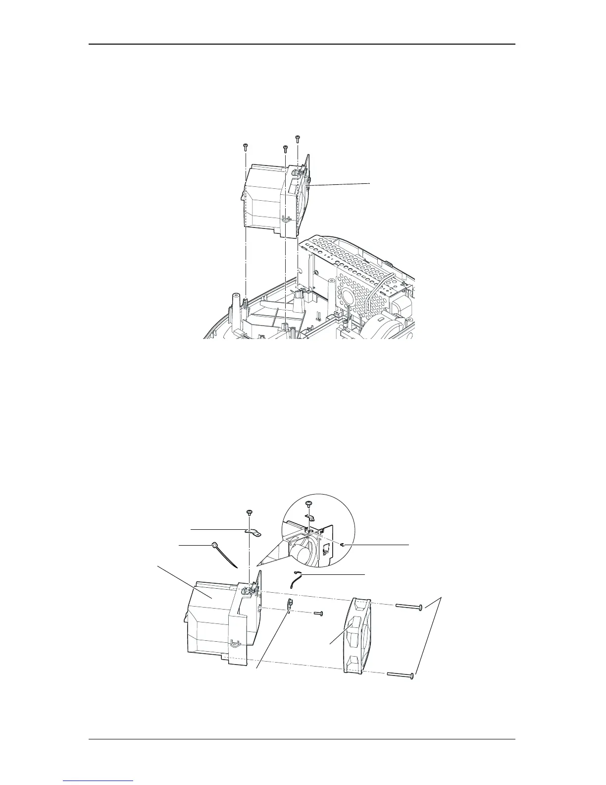
4.2.14 Removing the Exhaust Fan; B, Exhaust Duct, Inshulock T-18S, TH
Board Assy., C Cable; 170, MA Fasten Plate; PS, and Fasten Plate; A
1. Remove the three screws (C.B.P-TITE SCREW, 3x10, F/ZB-3C) that secure the Exhaust
Fan Assy., and remove the Exhaust Fan Assy.
Figure 4-36.
2. Remove the screw (C.C. SCREW, 3x6, F/ZN-3C) that secures the MA Fasten Plate; PS, and
remove the MA Fasten Plate; PS and Fasten Plate; A.
3. Cut off the Inshulock T-18S that secures the Exhaust Fan Cable and TH Board Cable.
4. Remove the screw (C.B.P-TITE SCREW, 3x10, F/ZB-3C) that secures the TH Board Assy.,
and remove the TH Board Assy. from the Exhaust Duct.
5. Remove the C Cable; 170 from the TH Board Assy.
6. Remove the two screws (C.B.P-TITE SCREW, 4x35, F/ZN-3C) that secure the Exhaust
Fan; B, and separate the Exhaust Fan; B from the Exhaust Duct.
Figure 4-37.
Exhaust Fan Assy.
Printed Circuit Board
Assembly; TH_R1
Exhaust Fan; B
Duct, Exhaust
C.B.P-TITE SCREW, 4x35, F/ZB-3C
Plate, Fasten; A
Plate, MA Fasten; PS
Inshulock T-18S
Cable, C; 170