2-14
EMP-TW1000
SEIKO EPSON Revision:A
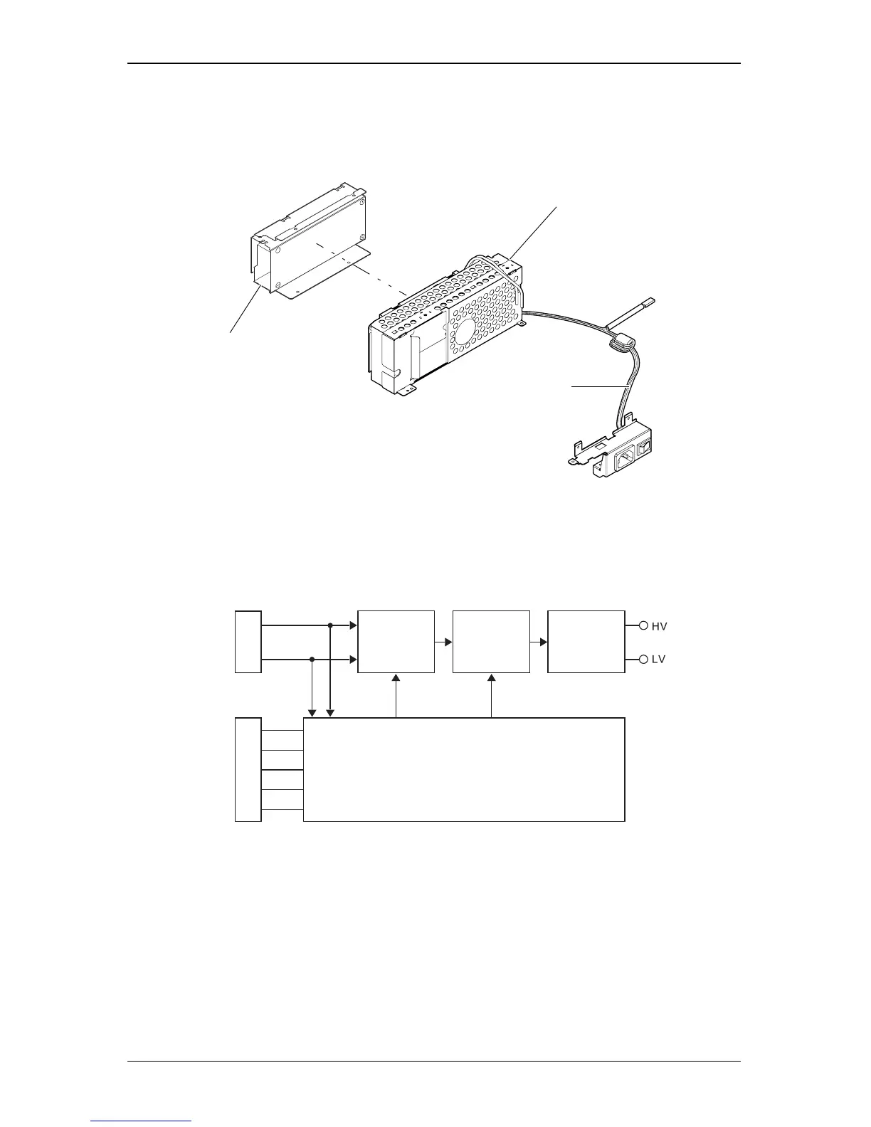
2.6 Ballast Unit
The Ballast Unit re-regulates a DC voltage (340-400VDC) supplied from the Power Supply
Unit, and generates 170W for the UHE lamp.
Figure 2-15. Ballast Unit
2.6.1 Power Supply Circuit Block Diagram
Figure 2-16. Power Supply Circuit Block Diagram
(1). Operating principles
• Control circuit : This generates the voltages (360V-400V DC) for the control circuit inside
the ballast unit. Re-regulation switching operations are carried out based
on the MA board output signal. The output voltage is adjusted to stabilize
the output power supply.
• Igniter circuit : Generates the 170W lamp voltage.
Ballast Unit
Cable AC
Power Supply Unit
DC Input
340-400V
To PS Unit
Down
Converter
H-bridge
Igniter
Ballast
Output 170W
Control Circuit
SCI Cable
To CN1501
on MA board