3-5
EMP-TW1000
SEIKO EPSON Revision:A
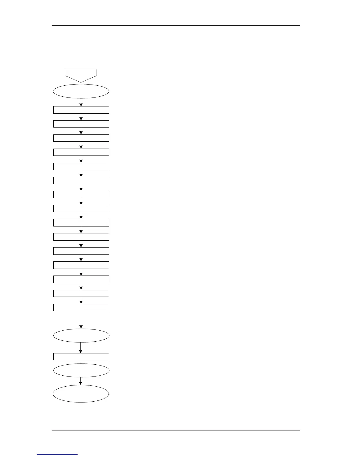
3.2.2 Internal Cable Check
Turn off the power and disconnect the power cable before you begin the following connector
checks. See Figure 2-2 on page 2-3 for the location of the MA Board connectors.
START
Upper Case Unit Removal
Control Panel • MA board CN1503 (Lock-type connector)
LV Fan/ PS Fan • MA board CN1304 (LV Fan)
• MA board CN1305 (PS Fan)
LAMP Themistor • MA board CN1301
Exhaust Fan • MA board CN1303
RC Boards • MA board CN1504 ↔ RC board (Front)
• MA board CN1505 ↔ RC board (Rear)
Lamp Lid Detection Switch
• MA board CN1500
Power Supply Unit • MA board CN4000
LV Th ermistor • MA board CN1300
Ballast • MA board CN1501
• Ballast unit ↔ Optical engine
Lamp Fan • MA board CN1302
Light Valve R/G/B • MA board CN2200/ 2500/ 2700 (Lock-type connector)
Cinema filter Motor • MA board CN1700
Cinema filter FD Switch • MA board CN1701
Auto Iris sensor • MA board CN1703
Auto Iris Motor • MA board CN1702
MA board Removal
IF Board • MA board CN1502
MA board Installation
Upper Case Unit
Installation