EPSON Stylus Color 980 Revision A
Disassembly and Assembly Disassembly Procedures 103
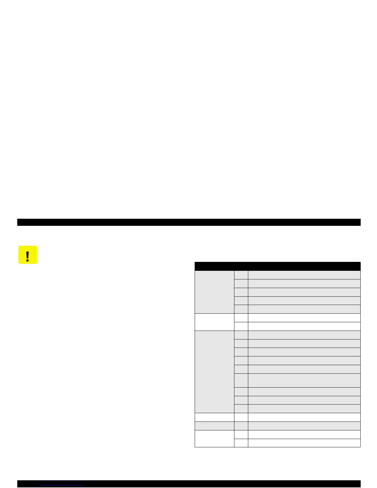
Table 4-1.
Removed/Replaced Parts and Corresponding Adjustments
CAUTION
If you have replaced specified parts, you must make
necessary adjustments. See the following tables which
shows the parts removed/replaced and corresponding
adjustments required, and perform adjustments in the
correct order. (See Chapter 5 “Adjustment” for detailed
procedures.)
Actions taken Step Corresponding adjustment required
Printhead 1 Install a new I/C in the I/C replacement sequence.
2 Head Actuator Voltage ID Input
3 Ink Charge Flag Reset
4 Head Angular Adjustment.
5 Bi-Directional Adjustment
C380 Main board 1 Head Actuator Voltage ID Input
2 Bi-Directional Adjustment
CR shaft 1 Remove the Printhead and CR Unit.
2 Remove the oil pad. (Refer to Chapter 6.)
3 Clean and lubricate the carriage guide shaft.
4 Reinstall the printhead and the CR Unit.
5 Perform the Parallelism adjustment.
6 Enter the I/C replacement sequence to install a new I/C
and make sure it is completed.
7 Ink Charge Flag Reset
8 Head Angular Adjustment
9 Bi-Directional Adjustment
Waste Ink Pad 1 Clear the protection counter value
CR Motor 1 Bi-Directional Adjustment
Program ROM
replacement
1 Head Actuator Voltage ID Input
2 Bi-Directional Adjustment
 Loading...


