EPSON Stylus Color 980 Revision A
Product Description Component Layout 40
1.7.4 C265 PNL Board
The C265 panel board is composed of the three switches and four
LEDs.
Figure 1-13. C265 PNL Board
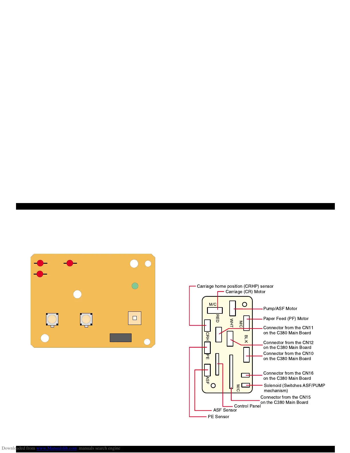
1.7.5 C265 Relay Board
The C265 relay board is installed to relay the following with connectors:
Power for driving motors and sensors
Control signals
If any of the connectors is connected to a wrong position during
assembly, the printer shows a fatal error at power on.
Figure 1-14. C265 Relay Board
LED 3
LED 2
LED 1
LED 0
SW 2 SW 1
SW 0
CN1
1
12
M/C
M/C
CRH PE ASF
RED
WHT
BLK
M/C
Carriage home position (CRHP) sensor
Carriage (CR) Motor
Pump/ASF Motor
Paper Feed (PF) Motor
Connector from the CN11
on the C380 Main Board
Connector from the CN12
on the C380 Main Board
Solenoid (Switches ASF/PUMP
mechanism)
Control Panel
ASF Sensor
PE Sensor
Connector from the CN10
on the C380 Main Board
Connector from the CN16
on the C380 Main Board
Connector from the CN15
on the C380 Main Board
 Loading...


