EPSON Stylus Color 980 Revision A
Operating Principles Printer Mechanism Operating Principles 46
2.2.2 Printing Mechanism
The printing mechanism of the printer is all included inside the
printhead. The printing method is EPSON-exclusive MACH system,
which is used in other EPSON ink jet printers, but the printhead is not
compatible with any other printer. See Figure 2-2 for the printing
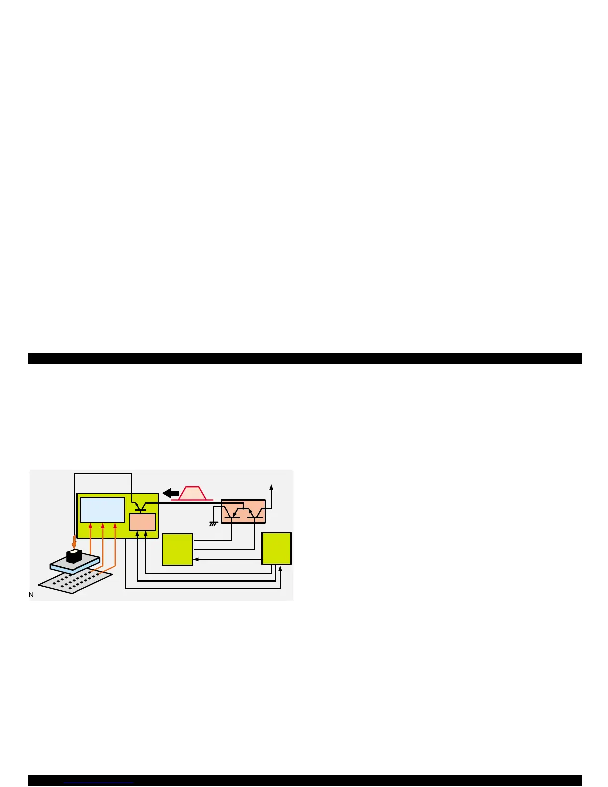
mechanism block diagram.
Figure 2-2. Printing Mechanism Block Diagram
The printing mechanism performs printing by applying voltage to the
PZT (integrated piezoelectric element) inside the printhead. With the
voltage applied to the PZT, the cavity, a tank filled with ink, is pressed
by the PZT and ejects ink from nozzles as the result. Unlikely to the
illustration, the actual number of the PZT included in the printhead in
this printer is 480, the same number as nozzles, and each PZT is
independently driven.
The steps below describes how the printing mechanism works.
1. Head drive pulse form command signal is output from the ASIC after
the printer is turned on.
2. Receiving the signal, the Pre-driver outputs the head drive pulse
signal to the driver.
3. If no printing data is sent, pulse output from the driver is not applied
to the PZT in the printhead: because the transistor on the nozzle
selector is not on.
4. If any printing data is sent from a PC, 5 serial data (3 for Y, M, and
C, and 2 for 2 rows of black) are sent to the nozzle selector from the
ASIC. Each serial data consists of 96 data since each row is
composed of 96 nozzles. When these data is all transferred, a Latch
signal is output from the ASIC to the nozzle selector after specified
period of time.
5. When the Latch signal is sent, a PZT signal is applied to the base
side of the transistor via the latch circuit in the nozzle selector.
6. Head drive pulse constantly output from the driver is then applied to
the PZT by the pulse output after a set of serial data and the latch
signal are all transferred.
7. The PZT drive pulse radiates large heat since it is driven with the
basic drive frequency of 32.4 K Hz and also has such a large
amount of drive elements as 480 PZT. Therefore, the abnormal
temperature detection circuit is included in the nozzle selector to
detect temperature of each nozzle so that heat radiation stays under
the maximum level. If the circuit detects abnormally high
temperature in any nozzle row, the printer regards the condition as
an accidental printing malfunction such as dot missing, and it
automatically enters the cleaning CL2, the most powerful cleaning
cycle. See the sensor descriptions in Chapter 2 for the operations
after this cleaning. The printhead also has the thermistor in it to
subtly change the voltage level of the drive pulse in accordance with
the temperature condition in use.
N o z z le
Selector
P re -
Driver
+42
Driver
Data
Latch
Charge
D is-charge
PZT
Cavity
 Loading...


