EPSON Stylus Color 980 Revision A
Operating Principles Electrical Circuit Operation Principles 67
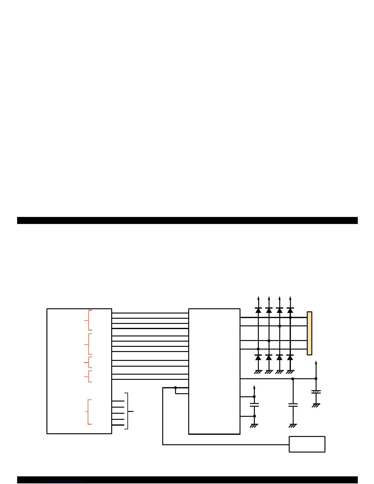
2.3.4 PF Motor Driver Circuit
Motor drive exclusive IC (LB1847: IC11) enables 4W1-2 phase
excitation on the hardware basis. A stepping motor is used for the PF
motor to move the carriage accurately and also to improve printing
accuracy by minimizing the motor’s vibration during printing. Figure
2-16 shows the PF motor driver circuit block diagram.
Figure 2-16. PF Motor Driver Circuit Block Diagram
+5
+42
+42 +42
+42
CN10
1
3
2
4
D/Axx
3
E05B 59(IC 2)
7
6
9
8
14
28
15
25
24
23
22
18
19
20
21
27
16
26
17
2
13
140
139
138
137
133
134
135
136
142
128
141
129
124
127
LB1847(IC 11)
125
126
123
N.C.
M 62383(IC 17)
+42
PFIA0
PFIA1
PFIA2
PFIA3
PFIB0
PFIB1
PFIB2
PFIB3
PFPHAA
PFPHAB
PFENBA
PFENBB
PFCTL0
PFCTL1
PFCTL2
PFCTLR
PFCTLS
Phase A setting
current signal
(16 patterns)
Phase B setting
current signal
(16 patterns)
Phase C R A(B)
selection signal
Phase C R A (B)
ENB (perm ission)
signal
M otor sub
control
IA 1
IA 2
IA 3
IA 4
IB 1
IB 2
IB 3
IB 4
PHASE1
PHASE2
ENABLE1
ENABLE2
VREF1
VREF2
OUTA
OUT-A
OUTB
OUT-B
VBB
VCC
GND
PFF
 Loading...


