EPSON Stylus Color 980 Revision A
Appendix Connector Summary 161
7.1 Connector Summary
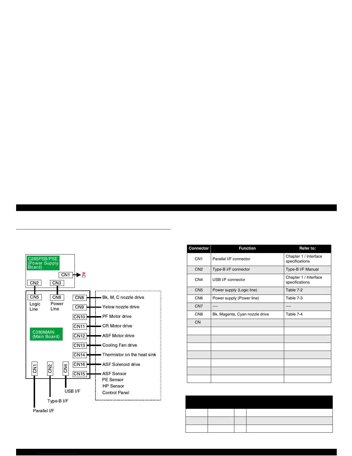
Figure 7-1 shows the cable connection of the Stylus Color 980.
Figure 7-1. Cable Connection of the Stylus Color 980
Table shows the connector assignment of the C380 Main Board.
Table 7-1. C380 Main Board Connections
Table 7-2. Connector Pin Assignment - CN5
C265PSB/PSE
(Power Supply
Board)
CN1
AC
CN2
CN5
CN8
C380MAIN
(Main Board)
CN1
CN2
CN10
CN11
CN4
PF Motor drive
ASF Sensor
PE Sensor
Parallel I/F
Type-B I/F
USB I/F
CN15
CN3
CN6
CN9
CN12
CN13
CN14
CN16
Bk, M, C nozzle drive
Yelow nozzle drive
HP Sensor
Control Panel
CR Motor drive
ASF Motor drive
Cooling Fan drive
Thermistor on the heat sink
ASF Solenoid drive
Logic
Line
Power
Line
Connector Function Refer to:
CN1 Parallel I/F connector
Chapter 1 / Interface
specifications
CN2 Type-B I/F connector Type-B I/F Manual
CN4 USB I/F connector
Chapter 1 / Interface
specifications
CN5 Power supply (Logic line) Table 7-2
CN6 Power supply (Power line) Table 7-3
CN7 ---- ----
CN8 Bk, Magenta, Cyan nozzle drive Table 7-4
CN9 Yellow nozzle drive Table 7-5
CN10 PF motor drive Table 7-6
CN11 CR motor drive Table 7-7
CN12 ASF motor drive Table 7-8
CN13 Cooling fan drive Table 7-9
CN14 Thermistor on the heat sink Table 7-10
CN15 Panel and Sensors (HP, PE, ASF) Table 7-11
CN16 ASF solenoid drive Table 7-12
Pin
Signal
Name
I/O Function
1, 7 GND ---- Ground
2, 3, 5, 6 5 V I +5 voltage supply
4 PSC I Delay control at power off
 Loading...


