EPSON Stylus Color 980 Revision A
Appendix Connector Summary 162
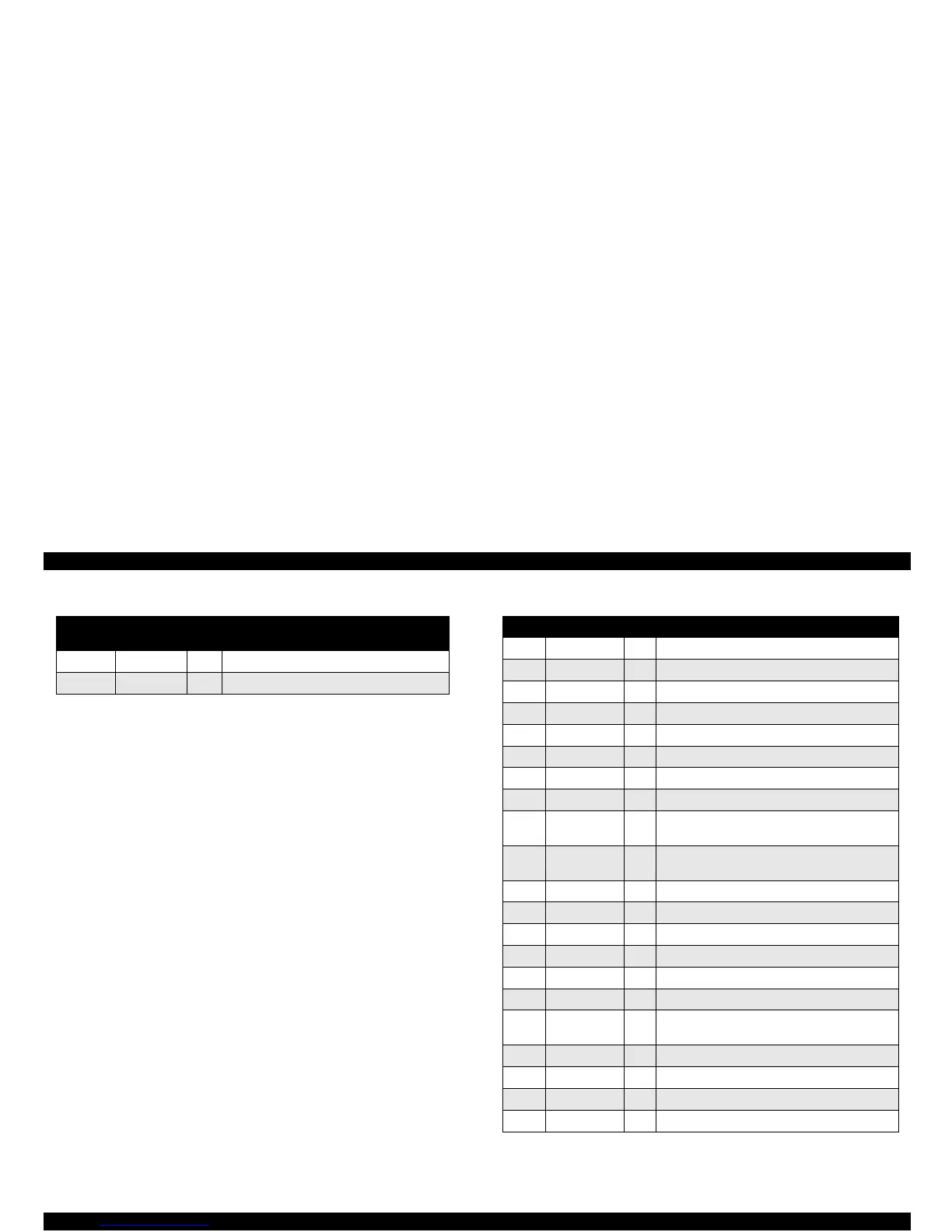
Table 7-3. Connector Pin Assignment - CN6 Table 7-4. Connector Pin Assignment - CN8
Pin
Signal
Name
I/O Function
1, 6 GND --- Ground
2, 3, 4, 5 +42 V I +42 voltage supply
Pin Signal Name I/O Function
1 ANODE1 I Row A temperature detection analog signal
2 ANODE2 I Row A temperature detection analog signal
3 GND2A --- Ground for the Nozzle Row A
4 GND2A --- Ground for the Nozzle Row A
5 COMa O Power voltage for the Nozzle Row A (black)
6 COMb O Power voltage for the Nozzle Row A (black)
7 GND2B --- Ground for the Nozzle Row B nozzles
8 GND2B --- Ground for the Nozzle Row B nozzles
9 ANODE3 I Row C (Cyan) temperature detection analog
signal
10 ANODE4 I Row D (Magenta) temperature detection analog
signal
11 GND2C --- Ground for the Nozzle Row C
12 GND2C --- Ground for the Nozzle Row C
13 COMc O Power voltage for the Nozzle Row C
14 COMd O Power voltage for the Nozzle Row D
15 GND2D --- Ground for the Nozzle Row D
16 GND2D --- Ground for the Nozzle Row D
17 VHV O Power supply for the comparator (Nozzle
Selector)
18 GND --- Ground
19 TH I Analog data from the thermistor on the printhead
20 LS2 I Phase B signal from the linear encoder
21 LS1 I Phase A signal from the linear encoder
 Loading...


