EPSON Stylus Color 980 Revision A
Disassembly and Assembly Disassembly Procedures 107
4. Disconnect two connectors CN5 and CN6 from the C380 Main
board and remove the C380 Main board unit.
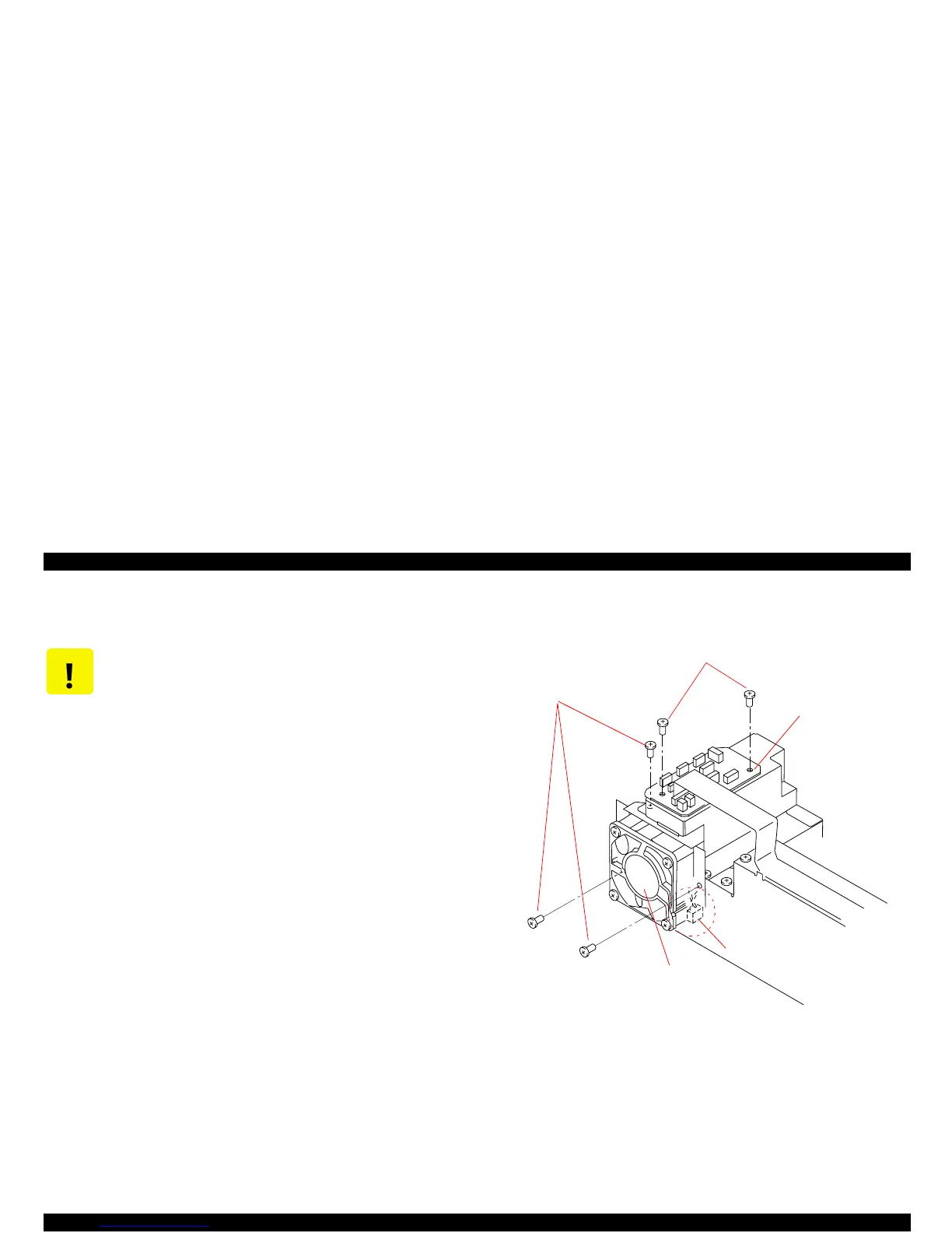
4.2.4 Relay Board and Cooling Fan Removal
1. Remove the C380 Main board unit. (See Section 4.2.3.)
2. Remove all connectors from the relay board. (See Figure 4-5 when
connecting them.)
3. Remove two screws securing the relay board to the shield plate on
the C380 Main board, then remove the relay board.
4. Remove three screws securing the cooling fan unit to the shield
plate on the C380 main board, then separate the cooling fan from
the C380 Main board.
5. Disconnect the connector CN13 (white, 2-pin) from the C380 Main
board, and remove the cooling fan unit.
Figure 4-8. Relay Board and Cooling Fan Removal
CAUTION
After removing/replacing the C380 Main Board,
perform any necessary adjustments. (See Table 4-1)
Screws securing the Relay Board
Screws securing the
Cooling Fan Unit
CN13
Relay Board
Cooling Fan Unit
 Loading...


