EPSON Stylus Color 980 Revision A
Operating Principles Electrical Circuit Operation Principles 65
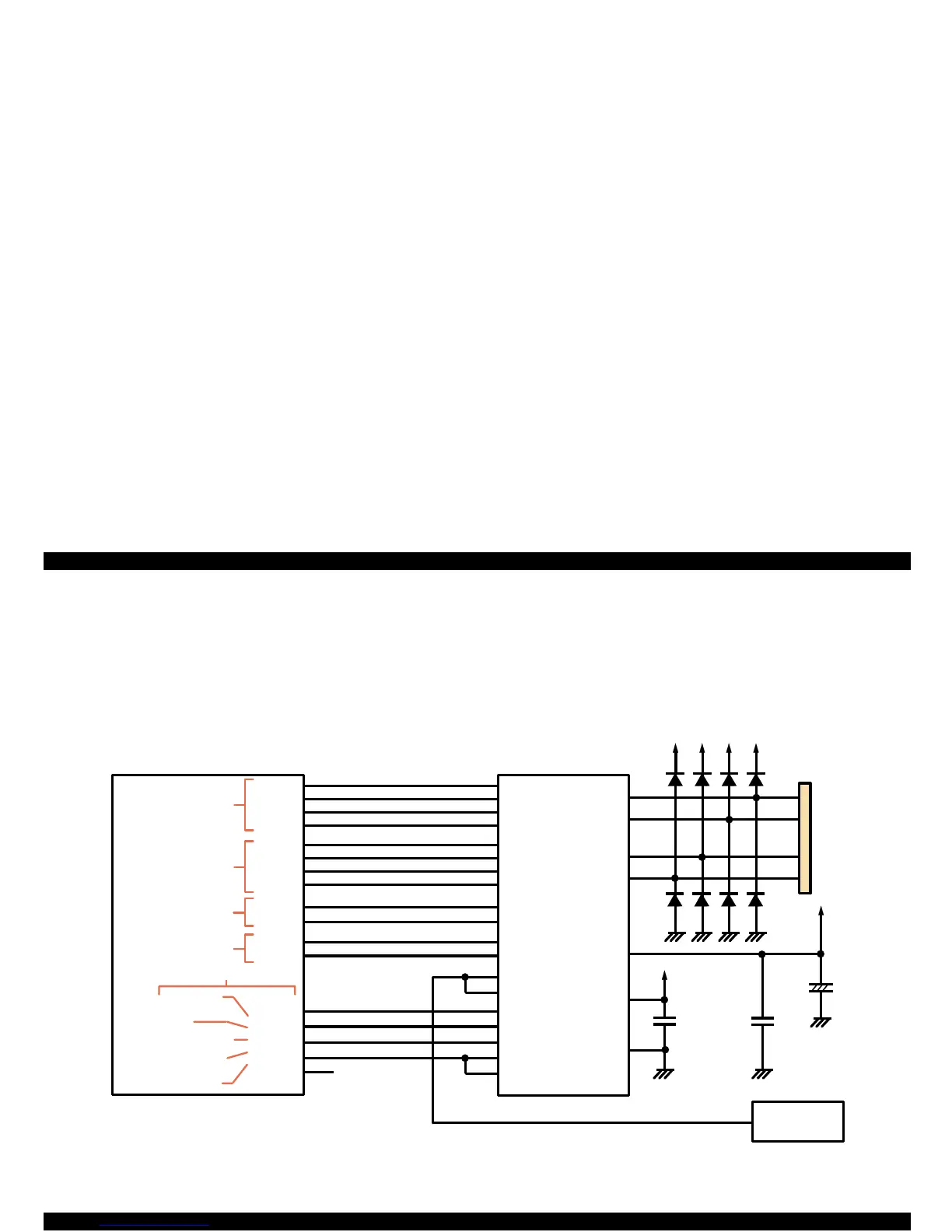
2.3.3 CR Motor Driver Circuit
An exclusive motor drive IC (LB1847: IC12) enables 4W1-2 phase
excitation on the hardware basis. A micro stepping motor is used for the
CR motor to move the carriage accurately and also to improve printing
accuracy by minimizing the motor’s vibration during printing. Figure
2-15 shows the CR motor driver circuit block diagram.
Figure 2-15. CR Motor Driver Circuit Block Diagram
+42
+5
+42
+42 +42
+42
CN11
1
2
3
4
D/Axy
8
E05B 59(IC 2)
7
6
9
8
14
28
15
25
24
23
22
18
19
20
21
27
16
26
17
2
13
3
12
147
148
149
150
163
162
161
160
143
170
144
169
171
172
LB1847(IC 12)
1
5
173
174
175
N.C.
M 62383(IC 17)
10
CRIA0
CRIA1
CRIA2
CRIA3
CRIB0
CRIB1
CRIB2
CRIB3
CRPHAA
CRPHAB
CRENBA
CRENBB
CRCTL0
CRCTL1
CRCTL2
CRCTLR
CRCTLS
Phase A setting
current signal
(16 patterns)
Phase B setting
current signal
(16 patterns)
Phase C R A(B)
selection signal
Phase C R A (B)
ENB (perm ission)
signal
M otor sub control
M D signal
DECAY signal 1
DECAY signal 2
N o t u s e d
Phase A constant
at chopping
IA 1
IA 2
IA 3
IA 4
IB 1
IB 2
IB 3
IB 4
PHASE1
PHASE2
ENABLE1
ENABLE2
VREF1
VREF2
CR1
CR2
MD
DECAY1
SECAY2
OUTA
OUT-A
OUTB
OUT-B
VBB
VCC
GND
OUT A
OUT-B
OUT-A
OUT B
 Loading...


