EPSON Stylus Color 980 Revision A
Operating Principles Electrical Circuit Operation Principles 69
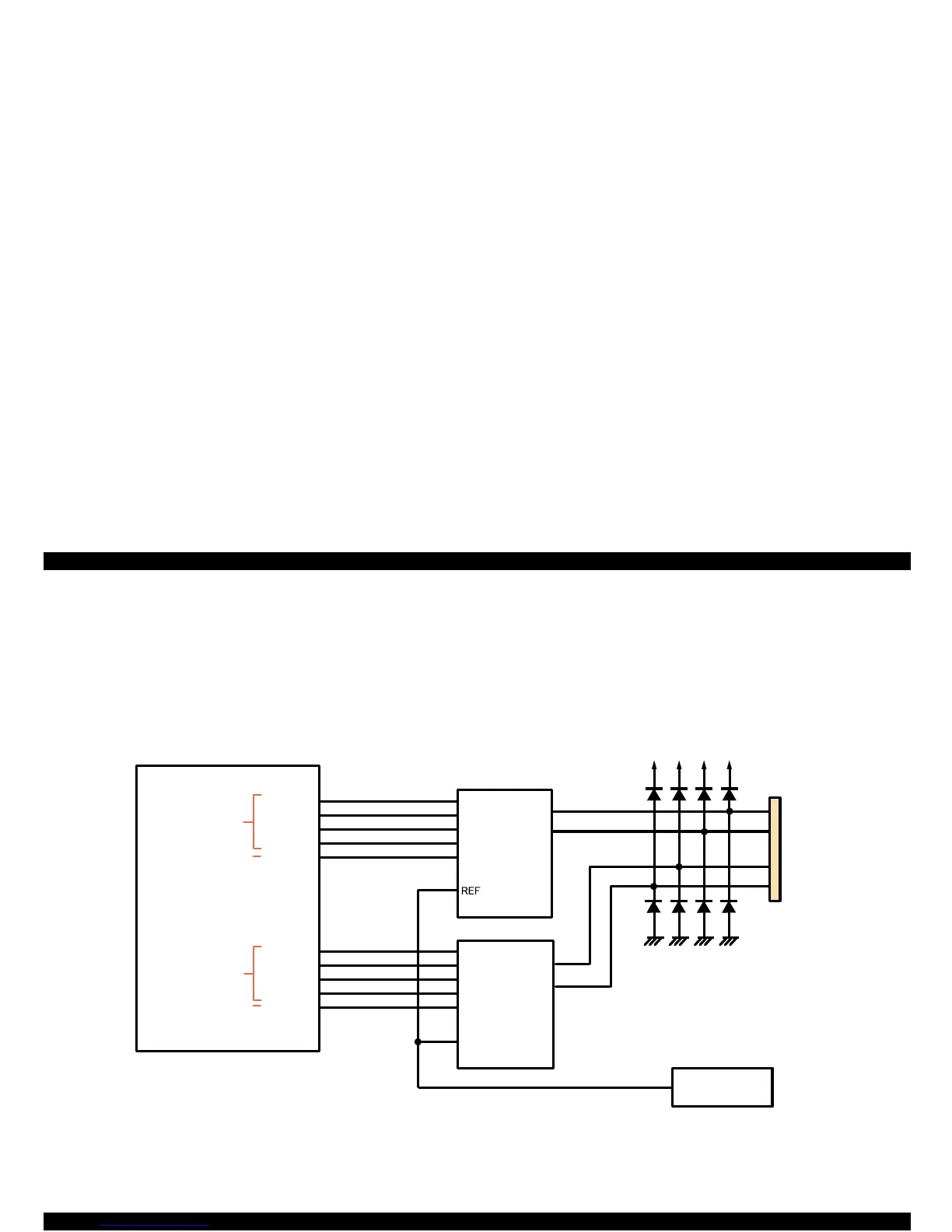
2.3.5 Pump/ASF Motor Driver Circuit
Like for the CR motor and the PF motor, A3957 (IC13, IC14) enables
the pump/ASF motor to perform 4W1-2 phase excitation on the
hardware basis. Figure 2-17 shows the pump/ASF motor driver circuit
block diagram. Among 2 drivers, IC13 and IC14 drives the Phase A and
Phase B, respectively.
Figure 2-17. Pump/ASF Motor Driver Circuit Block Diagram
+42
+42 +42
+42
CN12
1
3
2
4
A3957(IC 13)
15
22
A3957(IC 14)
15
22
REF
M 62383(IC 17)
D/Axy
4
20
13
11
8
10
20
13
11
8
10
E05B 59(IC 2)
69
68
62
64
63
81
80
72
74
73
ASFIA0
ASFIA1
ASFIA2
ASFIA3
ASFPHAA
ASFIB0
ASFIB1
ASFIB2
ASFIB3
ASFPHAB
ASF A
ASF -A
ASF B
ASF-B
Phase A specified
signal
Phase B specified
signal
Phase B setting
current signal
(16 patterns)
Phase A setting
current signal
(16 patterns)
OUTA
OUTB
OUTA
OUTB
 Loading...


