EPSON Stylus Color 980 Revision A
Operating Principles Electrical Circuit Operation Principles 60
[Sensor circuit]
The sensors attached to the printer are as described in the following
pages. They are basically divided into 2 major parts: 1) abnormal
temperature detection part and 2) mechanism status detection part. The
former is controlled by the CPU and the latter is controlled by 2 ASICs;
E05B59 (IC2) and E05B60 (IC3).
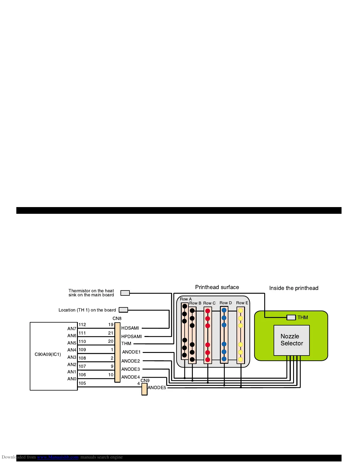
1) Abnormal temperature detection part
This abnormal temperature detection part is composed of 3 thermisotrs
and the temperature detection circuit which is included in the nozzle
selector inside the printhead. The CPU’s analog ports used for
temperature detection and their functions are as follows:
Figure 2-13. Sensor Circuit Block Diagram (Abnormal Temperature Detection Circuit)
ANODE5
CN8
CN9
THM
Nozzle
Selector
4
C90A09(IC1)
Thermistor on the heat
sink on the main board
Location (TH 1) on the board
AN7
AN6
AN5
AN4
AN3
AN2
AN1
AN0
112
111
110
109
108
107
106
105
19
21
20
1
2
9
10
HDSAMI
HPDSAMI
THM
ANODE1
ANODE2
ANODE3
ANODE4
Printhead surface
Inside the printhead
Row A
Row C
Row D
Row E
Row B
 Loading...


