EPSON Stylus Color 980 Revision A
Operating Principles Electrical Circuit Operation Principles 71
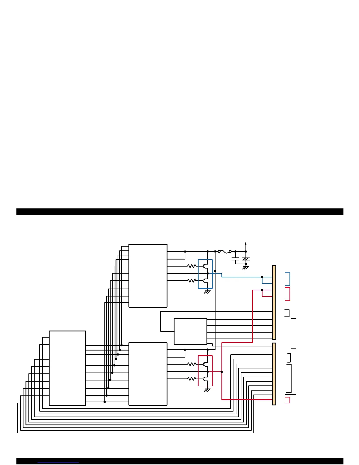
Figure 2-18. Printhead Driver Circuit Block Diagram
CN8
C X A2128(IC 15)
23
22
+42
C X A2128(IC 16)
5
17
6
13
14
20
18
16
23
22
20
18
16
28
27
26
25
3
4
5
29
30
1
28
27
26
25
3
4
5
29
30
1
114
113
112
111
120
119
118
115
116
121
E05B 59(IC 2)
AN0
AN1
AN2
AN3
AN4
CPU(IC1)
CN9
COM e
1
20
21
17
15
6
7
19
9
11
13
4
ANO DE5
AN5
105
106
107
108
109
110
19
1
2
9
10
110
109
107
102
97
98
99
100
101
108
Q3
Q4
Q5
Q6
F1
COC
COB
HLAT
HSOCLK
HSO_Y
HSO_M
HSO_C
HSO_B1
HSO_B2
HINV
HW A0
HW A1
HW A2
HW A3
HW CLK1
HW CLK2
/H W F L R
HW SDATA
HW SLC
/H W S L A T
A0
A1
A2
A3
CLK1
CLK2
/FLOOR
DATA
DCLK
/E
VCC45
VC C 45_2
NPNB
FB
PNPB
C harging/discharging
circuit for color nozzles
Black nozzle row s
C o lo r n o z z le r o w s
H ead tem perature
detection circuit
AN data
(tem perature
detection
for each color)
I/C detection signal
- D a ta la tc h s ig n a l
- N ozzle selection signal
- C lock signal
Trapezoid w aveform
reverse signal
C o lo r n o z z le r o w
C harging/discharging
circuit for black nozzles
A0
A1
A2
A3
CLK1
CLK2
/FLOOR
DATA
DCLK
/E
VCC45
VC C 45_2
NPNB
FB
PNPB
VHV
COM a
COM b
COM c
COM d
THM
ANO DE1
ANO DE2
ANO DE3
ANO DE4
COC
COB
LAT
CLK
Y
M
C
B1
B2
IN V
 Loading...


