EPSON Stylus Color 980 Revision A
Operating Principles Electrical Circuit Operation Principles 73
Whether or not the cooling fan is driven depends on the electrical
signals sent from the 2 thermistors (“t1” and “t2” in the figure). The “t1”
represents the temperature detected by the thermistor attached to the
heat sink on the C380 main board with a screw, while the “t2”
represents the one between the printhead pre-driver ICs (IC15 and
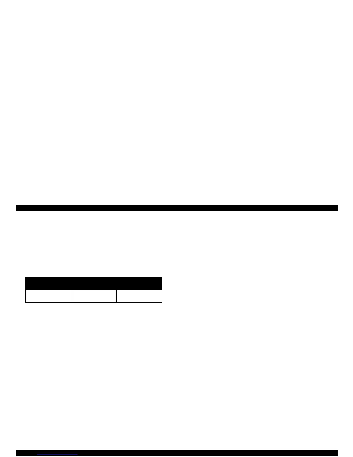
IC16) on the C380 main board. Table 2-20 shows the thermistor
condition and corresponding fan operation.
Table 2-20. Conditions for Driving the Cooling Fan
Even while the printer is in idle status, the thermistors continue to detect
temperatures every 2 seconds for the cooling fan operation. However, 2
error status conditions can be detected in the main routine, since air
may not cool down if the fan is defective or the ventilation grill is
clogged.
[Error 1]
The printer does not stop printing but continues to print by lowering the
drive frequency. For instance, the printer normally prints with the head
drive frequency of 14.4 K Hz to perform 1440-dpi print (horizontal) at
200 cps (CR speed). In the error condition, however, the printer can
lower the head drive frequency to 7.2 K Hz by reducing CR speed to
100 cpi. Note the printer actually performs printing at 1/3 duty / 1-pass
of a normal speed.
[Error 2]
The printer stops printing. In this condition, the temperature at the
junction of the power transistor for trapezoidal waveform production and
the trapezoid waveform production IC (pre-driver) has risen to the limit
(which means the thermistors have detected over 60
°
C at both t1 and
t2), and the printer generates a fatal error after stopping printing
completely. Therefore, this printer specifically shows a fatal error on the
control panel when detecting abnormal temperatures in addition to the
following 2 common conditions.
1. Failure in CR home position detection:
This failure can be caused by one of the following 4 reasons:
- CRHP sensor itself is defective.
- There is a deficiency in the circuit.
- Incorrect PG adjustment
- CR motor is defective
2. Failure in ASF home position detection:
This failure can be caused by one of the following reasons:
- ASF sensor itself is defective.
- There is a deficiency in the circuit.
- ASF is damaged.
- Pump/ASF motor is defective.
Thermistor condition
Cooling fan:
Operating
Cooling fan:
Stops operating.
t1 and t2 have detected
temperatures.
t1
≥
°
40 C or t2
≥
50
°
Ct1
≥
°
36 C or t2
≥
42
°
C
 Loading...


