EPSON Stylus Color 980 Revision A
Troubleshooting Overview 91
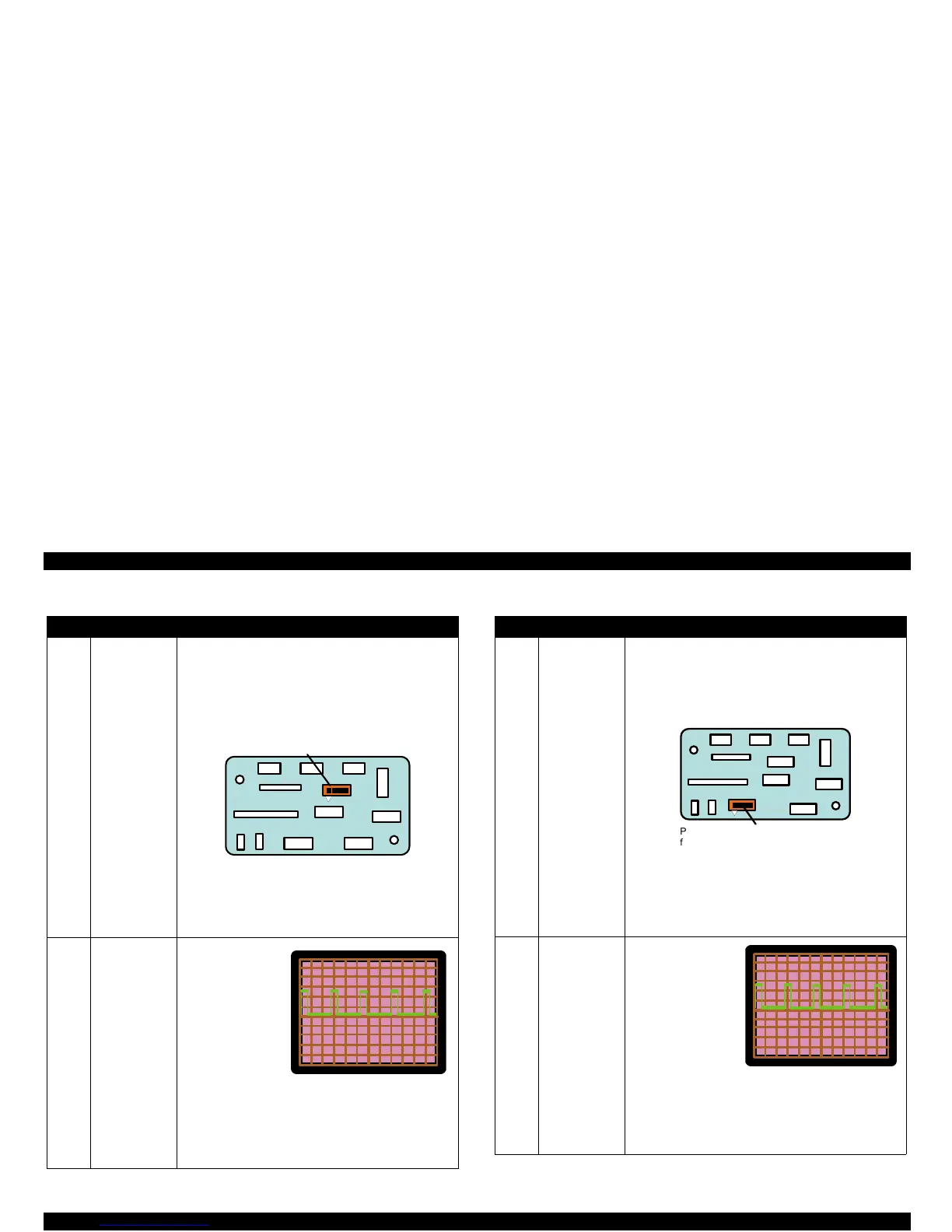
Table 3-23. CR Motor does not Operate Table 3-24. PF Motor does not Operate
Step Check Point
Action
1 Getting ready
for inspecting
waveforms.
The connector used to control the CR motor is indicated
in the figure below. Using the oscillo scope, check for the
waveform for each phase at the indicated connector.
To check the waveform, press the Load/Eject button to
attempt to move the carriage. Be sure to leave the cable
for the CR motor connected.
NOTE:
The GND can be output by placing the probe of
the oscillo scope to the tapped hole in the
bottom plate on the board with a screw. Note
the connector has no ground line since this
printer drives the motor with the bipolar system.
2 Check of the
waveform and
remedies
While trying to drive
the CR motor, the
waveform output
from each phase
should be as shown
in the figure. If the
waveform output
from each phase is
as shown below,
replace the CR
motor. If not,
replace the IC12 (CR motor driver IC) or C380 Main
board.
NOTE:
The GND can be output by placing the probe of
the oscillo scope to the tapped hole in the
bottom plate on the board with a screw.
M/C
M/C
CRH PE ASF
RED
WHT
BLK
M/C
Phase A , P hase B , P hase /A , and
Phase /B from the P in 1 m ark.
20V
20
m
Step Check Point
Action
1 Getting ready
for inspecting
waveforms.
The connector used to control the PF motor is indicated
in the figure below. Using the oscillo scope, check for the
waveform for each phase output from the indicated
connector. To check the waveform, press the Load/Eject
button to attempt the ASF paper feeding. Be sure to
leave the cable for the PF motor connected.
NOTE:
The GND can be output by placing the probe of
the oscillo scope to the tapped hole in the
bottom plate on the board with a screw. Note
the connector has no ground line since this
printer drives the motor with the bipolar system.
2 Check of the
waveform and
remedies.
While trying to drive
the PF motor, the
waveform output from
each phase should be
as shown in the
figure. If the
waveform output from
each phase is as
shown in the figure,
replace the PF motor.
If not, replace the
IC11 (PF motor driver IC) or C380 Main board.
NOTE:
The GND can be output by placing the probe of
the oscillo scope to the tapped hole in the
bottom plate on the board with a screw.
 Loading...


