2.5.2.4 Timer Circuit
A lithium battery is mounted on the main board and calculates how long the printer is
not used. The timer IC starts counting with oscillation motivated by the crystal
oscillator using this battery as a power source. The following figures show connection
of the Timer circuit. The followings explain about operation of this circuit.
n When the printer is on, power is supplied to the Timer IC by applying +5V
quickly through the D1.
n This power is also used for the power to oscillator. The oscillation wave form is
input to XI terminal.
n Since the oscillation wave form of CR1 is analog wave form, it is processed into
the pulse form in the Timer IC.
n When the printer is turned on, the Timer IC outputs power off time as serial data
to the gate array.
n Once the printer is turned off, 3VDC of BAT1(lithium battery) is supplied as
power source for the Timer IC through D7.
n Since +5V at the power on is higher than +3V of the lithium battery, the power is
not being consumed from the lithium battery.
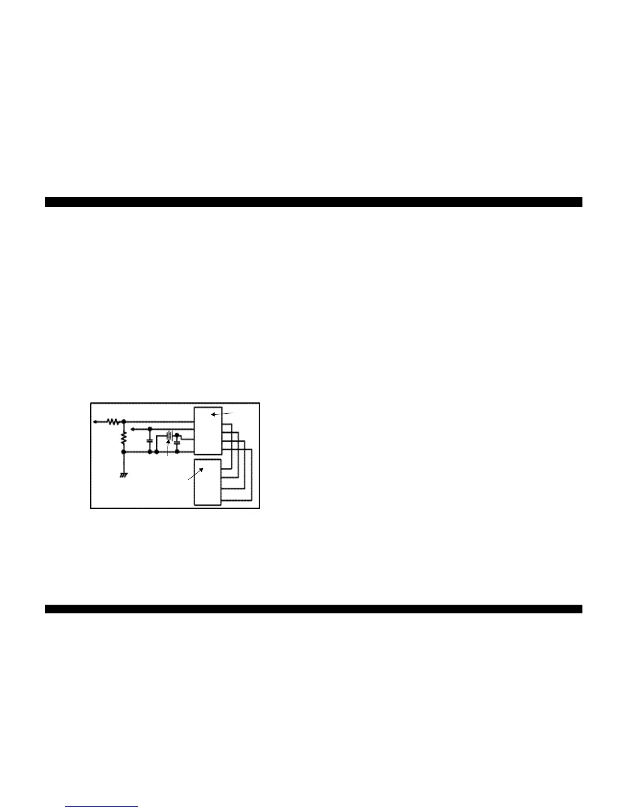
Figure 2-29. Timer Counter Circuit
+42
+5 7
9
8
14
Batt 1
RTC-9810
(ICB)
Vin
Vdd
Vbk
GND
Data
SCL
CE
/RST
2
6
5
4
25
20
21
23
E05B588
(IC2)
TMCS
TMCK
TMCS
TMDATA
 Loading...