Appendix D-58 Product Overview Rev.D
Confidential
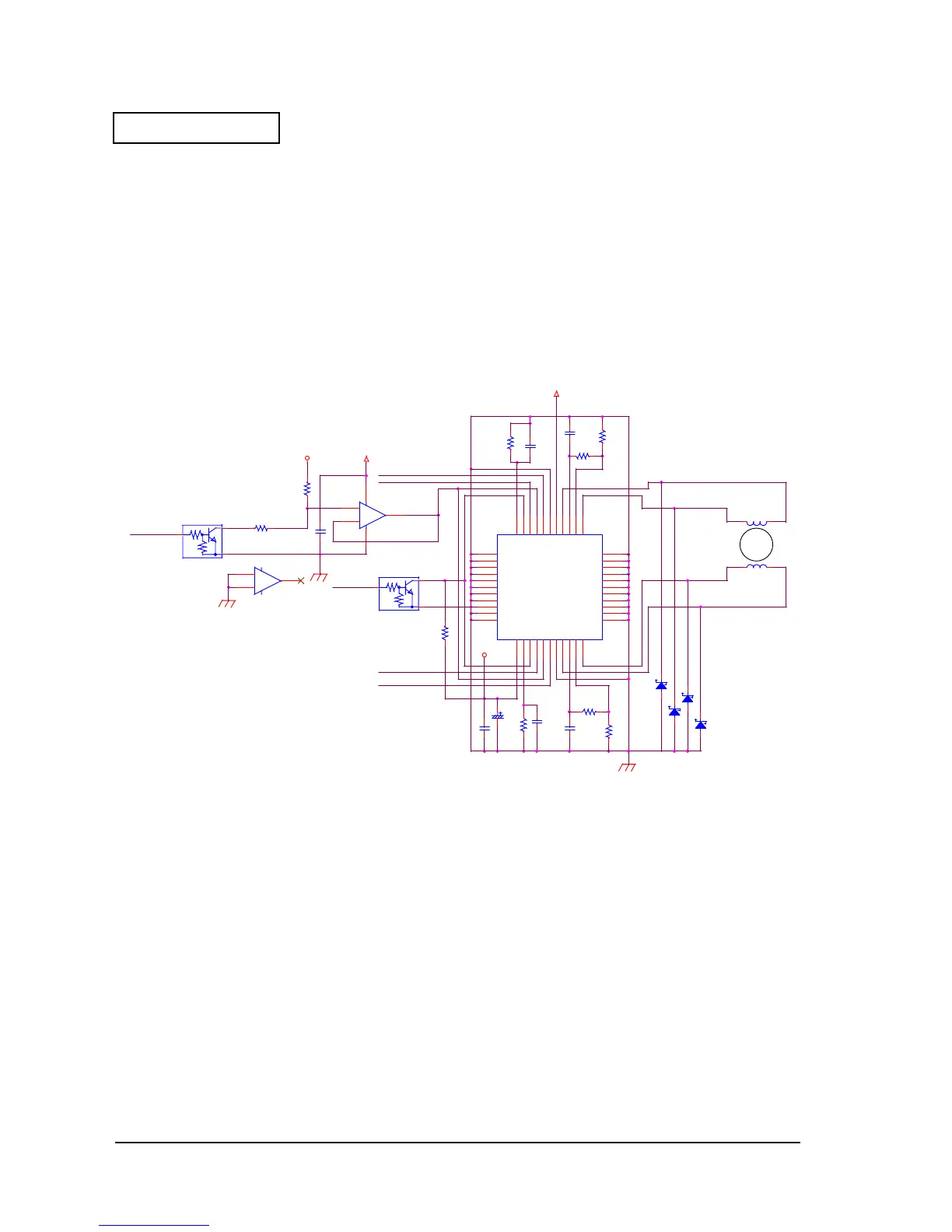
The drive signal to drive the phases is sent at the logical level of the PHASE1, 2 terminals. The
motor driver cannot operate unless signal 24VSW1 in the circuit diagram is set to HIGH
(controlled by the GA). When this signal is at a status other than HIGH, IC consumption is 0,
and no electricity goes to the motor.
Slip Paper Feed Motor Drive Circuit
The slip paper feed motor is two-phase stepping motor. The driving method is 1-2 phase
excitation during acceleration and deceleration, and constant-current drive is performed with
2-2 phase excitation. Therefore, a dedicated constant-current drive chopping driver (U17,
A2917SEB made by Alegrow) is used.
Figure D-54
The circuit configuration is the same as the carriage motor driver, but the current setting is fixed,
and is changed between two levels by the output (PF_HOLD) of the GA (U30) port. The current
calculation procedure is described below.
Current = VREF/(10 ✕
Rs)
RS: 1
Ω
VREF: VCC or voltage obtained by voltage division ratio of R105 and R106.
As for the carriage motor drive circuit, the driver IC is operated by setting the 24VSW1 signal
HIGH.
VCC-PWR
24VCVCC
24VC
M
SLIP-PF
PF_I21
PF_A+
PF_A-
PF_B+
PF_B-
PF_I11
PF_PH2
PF_PH1
PF_HOLD
24VSW1
R102
1
1W
1%
12
R117
1K
1 2
C54
47uF
6.3V
PN
R103
75K
12
U17
A2917SEB
OUT1A
6
E1
5
SENSE1
4
OUT1B
3
I10
2
I11
1
VREF1
44
PHASE1
43
ENABLE1
42
RC1
41
LOGIC SPLY
40
OUT2A
18
E2
19
SENSE2
20
OUT2B
21
LOAD SPLY
22
I20
23
I21
24
VREF2
25
PHASE2
26
ENABLE2
27
RC2
28
G
29
G
30
G
31
G
32
G
33
G
34
G
35
G
36
G
37
G
38
G
39
G
17
G
16
G
15
G
14
G
13
G
12
G
11
G
10
G
9
G
8
G
7
C57
3300pF
12
D29
EC10QS06
1 2
R104
1K
1 2
R118
75K
12
C49
3300pF
1 2
D26
EC10QS06
1 2
D30
EC10QS06
1 2
R119
1
1W
1%
12
R113
3.3K
1 2
C55
470pF
12
D27
EC10QS06
1 2
C56
0.1uF
12
C50
470pF
12
R105
68K
1%
1 2
R106
30K
1%
12
+
-
U16B
NJM2904M
5
6
7
Q30
DTC114EK
2
3
1
C53
0.1uF
12
+
-
U16A
NJM2904M
3
2
1
84
Q18
DTC114EK
2
3
1

 Loading...


