Hardware
The eSID3 is completely redesigned from eSID2 and has lower quiescent current (1.8mA) and also
supports:
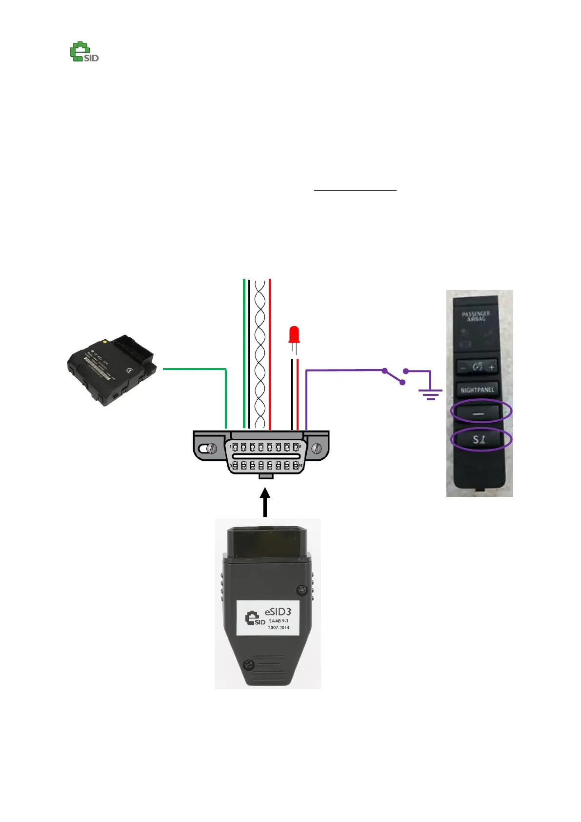
Configurable switch input interface
Configurable 12V output driver for LED or Relay with fly back diode (max 200mA)
Simplified interface to set System Clock time when using non-OEM radio/Nav.
The new interfaces are used by connecting additional wires to unused pins in the OBD-connector.
The cables needed are sold separately in “eSID3 Cable Kit”.