Name of document:
eSID3 User Guide
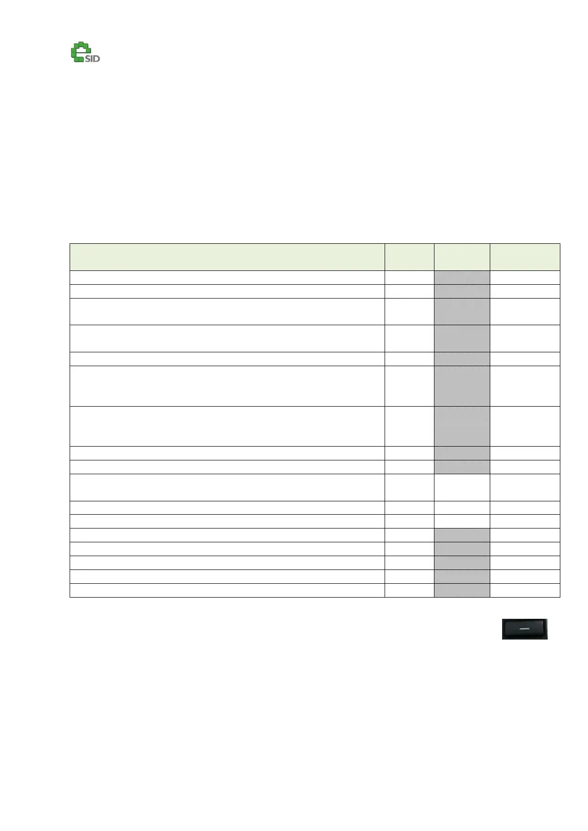
Digital Output Logic/Threshold/Source
Description
This is the configuration of the 12V Digital Output.
Enable Criteria
Output logic enabled on all vehicles
Threshold setting is only enabled if the selected logic has a threshold
Configuration Options
eSID3 Switch Input - Output active when is Switch is Pushed
1
eSID3 Switch Input – Output changes state on Switch Push/Release.
Output is always inactive on next Key Cycle
2
eSID3 Switch Input – Output changes state on Switch Push/Release.
Output remembers the previous state on next Key Cycle
Output is active when Key is inserted into the Ignition Switch
SAAB Extra Light Switch
3
– Output changes state on Switch
Push/Release. Output is always inactive on next Key Cycle
Note: It can take up to 3 seconds before output state changes
SAAB Extra Light Switch
3
– Output changes state on Switch
Push/Release. Output remembers the previous state on next Key
Cycle. Note: It can take up to 3 seconds before output state changes
Output is active when Reverse Gear is active
Output is controlled by External CAN Interface
4
Output is active when the Engine Speed is above threshold
(On software SG1.1.x and forward only in MT-mode on AT-cars)
Output is active when the Vehicle Speed is above threshold
Output is active when the Accelerator Pedal is above threshold
Output is active when High beam is Active
Output is active when Auxiliary Relay (Extra Light) is active
Output is active when Unlock Light is active
Output is active when Ignition Key is in OFF and ON
Output is active when Ignition Key is in ON
1
Pushed=Switch grounded, Released=Open circuit
2
New Key Cycle is when Key is inserted into Ignition Switch
3
The Extra Light switch is the one normally used for extra headlight. No separate wiring needed.
4
Will be explained in separate document
User Inputs
SET – Enter or Exit Edit mode (***)
INFO UP/DN – Change Setting in Edit mode.