Home
Evolis
Printer
Primacy
Service Manual
Page 45 (Step 21 - Stepper Motor - S10096)
Evolis Primacy - Step 21 - Stepper Motor - S10096; Picture 47: Stepper Motor; Picture 48: Transport Belt
61 pages
Manual
Save Page as PDF
To Next Page
To Next Page
To Previous Page
To Previous Page
Loading...
Primacy Service Manual
45
/
61
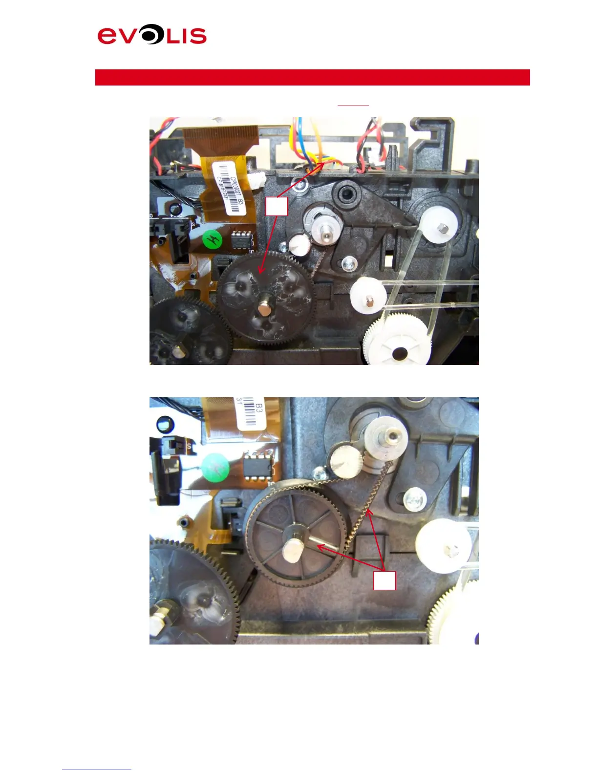
Step 21
–
STEPP
ER MOTOR
–
S1009
6
1.
First, be sure to have completely performed
Step 18
.
2.
Remove the motor cable and the gear.
Picture 47: Stepper Motor
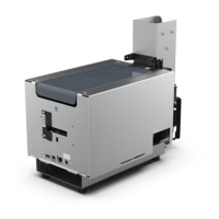
3.
Remove the MXL belt and the gear.
Picture 48: Transport Belt
2
3
44
46
Table of Contents
Main Page
Table of Contents
2
Introduction
3
Liability Statement
3
Proprietary Notice
3
Trademark Acknowledgments
3
Environmental Information - Recycling of End-Of-Life Products
3
Operator
4
Mechanical Maintenance Personnel
4
Electrical Maintenance Personnel
4
Symbols
5
Safety
6
Safe Environment
6
Safe Human Interface
6
General Safety Regulations
7
Picture List
8
Description
10
Picture 1: Evolis Primacy Printer
10
Explode View
11
Drawing 1
11
Drawing 2
12
Drawing 3
12
Drawing 4
13
Drawing 5
14
Drawing 6
15
Drawing 7
16
Drawing 8
16
Drawing 9
17
Spare Parts List
18
Available Tools
19
Picture 2: Tools
19
Step 1 - Reject Box - Ci010222
20
Picture 3: Reject Box
20
Step 2 - Enclosure Side - Ci010214
21
Picture 4: Top Cover
21
Picture 5: Side Bolt
21
Picture 6: Enclosure Side
21
Step 3 - Lcd Control Panel (with Cable) - S10086
22
Picture 7: Control Panel
22
Step 4 - Upper and Hopper Feeder - S10123 to S10126
23
Picture 8: Feeder Inside Right Side
23
Picture 9: Feeder Inside Left Side
23
Picture 10: Feeder Front Side
23
Picture 11: Feeder Right Side
24
Picture 12: Feeder Left Side
24
Step 5 - Feeder Belts Kit - S10092
25
Picture 13: Feeder Belt
25
Step 6 -Tighting Belts Kit - S10094
26
Picture 14: Feeder Tighting Belt
26
Picture 15: Feeder Tighting Belt-1
26
Step 7 - Common Motor - S10097 ( Feeder)
27
Picture 16: Feeder E-Ring & Pulley
27
Picture 17: Feeder Motor Cable
27
Picture 18: Feeder Motor-1
28
Picture 19: Feeder Motor-2
28
Step 8 - Enclosure Base - Ci011190
29
Picture 20: Enclosure Base Side
29
Picture 21: Enclosure Base Clip-1
29
Picture 22: Enclosure Base Clip-2
29
Step 9 - Flip over Sensor - S10121
30
Picture 23: Flip Sensor
30
Step 10 - Ribbon Braking Kit- S10093
31
Picture 24: Ribbon Lock
31
Picture 25: Ribbon Lock Details
31
Picture 26: Ribbon Lock Gear
32
Step 11 - Transport Belts Kit - S10091
33
Picture 27: Transport Belt
33
Picture 28: Black Ribbon Belt
33
Picture 29: Tansport Belts
34
Picture 30: MLX Transport Belt
34
Step 12 - Ribbon Detection Kit - S10087
35
Picture 31: Ribbon Detection
35
Picture 32: Ribbon Detection Rivet
35
Step 13 - Stepper/Feeder Motor - S10098
36
Picture 33: Motor Flip
36
Step 14 - Flip over Module - S10128
37
Picture 34: Flip Sensor
37
Picture 35: Flip Motor
37
Picture 36: Flip Support
38
Picture 37: Flip over
38
Step 15 - Cleaning Roller - S10122
39
Picture 38: Cleaning Roller
39
Step 16 - I/O Shield - Ci010322
40
Picture 39: I/O Shield
40
Step 17 - Enclosure Bottom Plate - Se010079
41
Picture 40: Bottom Plate
41
Step 18 - Main Board Usb Eth - S10114
42
Picture 41: Mainboard Connections
42
Picture 42: Fixing Mainboard
42
Step 19 - Common Motor - S10097 (up and Down)
43
Picture 43: Gear Motor
43
Picture 44: Motor Clip
43
Step 20 - Common Motor- S10097 (Ribbon)
44
Picture 45: Common Motor Left Side
44
Picture 46: Common Motor Clip
44
Step 21 - Stepper Motor - S10096
45
Picture 47: Stepper Motor
45
Picture 48: Transport Belt
45
Picture 49: Belt Idler Screws
46
Picture 50: Stepper Motor
46
Picture 51: Black Gears Position
46
Step 22 - Head Roller Kit - S10099
47
Picture 52: Left Side Components
47
Picture 53: Stepper Belt
47
Picture 54: Transport Belt
48
Picture 55: Disassembly Chassis Screws
48
Picture 56: Separation of Chassis
49
Picture 57: Synchro Ribbon Support
49
Picture 58: Option Roller & Springs
50
Picture 59: Heat Roller -1
50
Picture 60: Heat Roller - 2
50
Step 23 - Flex Sensor Kit - S10088
51
Picture 61: Flex Connector
51
Picture 62: Flex Rivets
51
Picture 63: Flex Card Sensor
52
Step 24 - Print Head (Kpe) - S10084
53
Picture 64: Print Head - 1
53
Picture 65: Print Head - 2
53
Picture 66: Print Head - 3
53
Step 25 - Ribbon Sensor - S10089
54
Picture 67: Ribbon Sensor - 1
54
Picture 68: Ribbon Sensor - 2
54
Picture 69: Ribbon Sensor - 3
54
Step 26 - Enclosure Cover - Ci010205
55
Picture 70: Enclosure Cover - 1
55
Picture 71: Enclosure Cover - 2
55
Step 27 - Enclosure Buttom - Ci010206
56
Picture 72: Enclosure Button
56
Step 28 - Fan Kit - S10100
57
Picture 73: Fan - 1
57
Picture 74: Fan Connector
57
Picture 75: Fan Cable Path
58
Picture 76: Fan - 2
58
Step 29 - Print Head Cable - S10085
59
Picture 77: Print Head Cable - Print Head Connector
59
Picture 78: Print Head Cable - Mainboard Connector
59
Picture 79: Print Head Cable Path
59
Step 30 - Head Bracket - S10138
60
Picture 80: Head Bracket Connectors
60
Picture 81: Head Bracket Cables Path
60
Picture 82: Head Bracket Axis
60
Evolis Contact
61
Other manuals for Evolis Primacy
User Guide
65 pages
Related product manuals
Evolis PRIMACY 2
74 pages
Evolis KC PRIME
27 pages
Evolis Pebble
49 pages
Evolis Pebble 4
51 pages
Evolis New Pebble
36 pages
Evolis Primacy Lamination
68 pages
Evolis Zenius
63 pages
Evolis Dualys
61 pages
Evolis Avansia
81 pages
Evolis Dualys 3
51 pages
Evolis badgy 100
37 pages
Evolis badgy 200
37 pages