Primacy Service Manual
8 / 61
Picture list
Drawing 1 ............................................................................................................................................................. 11
Drawing 2 ............................................................................................................................................................. 12
Drawing 3 ............................................................................................................................................................. 12
Drawing 4 ............................................................................................................................................................. 13
Drawing 5 ............................................................................................................................................................. 14
Drawing 6 ............................................................................................................................................................. 15
Drawing 7 ............................................................................................................................................................. 16
Drawing 8 ............................................................................................................................................................. 16
Drawing 9 ............................................................................................................................................................. 17
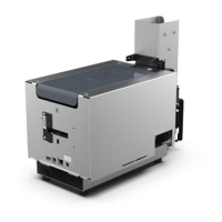
Picture 1: Evolis Primacy printer ................................................................................................................. 10
Picture 2: Tools ............................................................................................................................................. 19
Picture 3: Reject Box ................................................................................................................................... 20
Picture 4: Top Cover .................................................................................................................................... 21
Picture 5: Side Bolt ....................................................................................................................................... 21
Picture 6: Enclosure Side ............................................................................................................................ 21
Picture 7: Control Panel .............................................................................................................................. 22
Picture 8: Feeder inside Right Side ............................................................................................................ 23
Picture 9: Feeder inside Left Side ............................................................................................................... 23
Picture 10: Feeder Front Side ...................................................................................................................... 23
Picture 11: Feeder Right Side ..................................................................................................................... 24
Picture 12: Feeder Left Side ........................................................................................................................ 24
Picture 13: Feeder Belt ................................................................................................................................ 25
Picture 14: Feeder Tighting Belt .................................................................................................................. 26
Picture 15: Feeder Tighting Belt-1 .............................................................................................................. 26
Picture 16: Feeder E-ring & pulley ............................................................................................................. 27
Picture 17: Feeder Motor Cable ................................................................................................................. 27
Picture 18: Feeder Motor-1 ......................................................................................................................... 28
Picture 19: Feeder Motor-2 ......................................................................................................................... 28
Picture 20: Enclosure Base side ................................................................................................................. 29
Picture 21: Enclosure Base clip-1 ............................................................................................................... 29
Picture 22: Enclosure Base clip-2 ............................................................................................................... 29
Picture 23: Flip Sensor ................................................................................................................................. 30
Picture 24: Ribbon lock ............................................................................................................................... 31
Picture 25: Ribbon lock details .................................................................................................................. 31
Picture 26: Ribbon lock gear ...................................................................................................................... 32
Picture 27: Transport Belt ............................................................................................................................. 33
Picture 28: Black Ribbon Belt ..................................................................................................................... 33
Picture 29: Tansport Belts ............................................................................................................................ 34
Picture 30: MLX Transport Belt .................................................................................................................... 34
Picture 31: Ribbon Detection...................................................................................................................... 35
Picture 32: Ribbon Detection Rivet ............................................................................................................ 35
Picture 33: Motor Flip ................................................................................................................................... 36
Picture 34: Flip Sensor ................................................................................................................................. 37
Picture 35: Flip Motor ................................................................................................................................... 37
Picture 36: Flip Support ............................................................................................................................... 38
Picture 37: Flip Over .................................................................................................................................... 38
Picture 38: Cleaning Roller ......................................................................................................................... 39
Picture 39: I/O Shield .................................................................................................................................. 40
Picture 40: Bottom Plate .............................................................................................................................. 41
Picture 41: MainBoard Connections .......................................................................................................... 42
Picture 42: Fixing MainBoard ...................................................................................................................... 42
Picture 43: Gear Motor ................................................................................................................................ 43
Picture 44: Motor Clip .................................................................................................................................. 43
Picture 45: Common Motor Left Side ......................................................................................................... 44