30
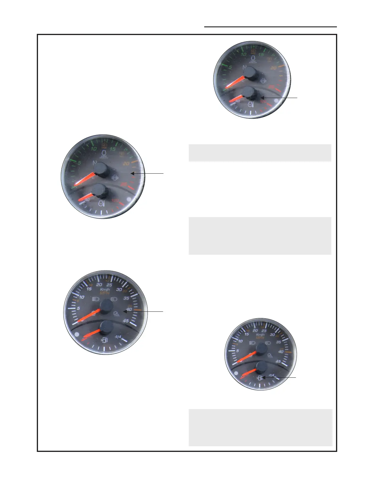
3.4 RPM Meter
The RPM meter indicates engine revolutions per
minute.
The yellow marks of 540 and 540E (Economy PTO)
on RPM scales indicates the engine speed at which
PTO RPM of 540 and 540E is obtained respectively.
The hours recorded should be used as a guide to
determine hours servicing intervals.
1
Figure-17
1. RPM Meter
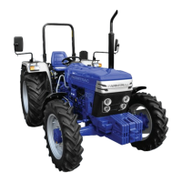
3.5. Speed Meter
It Indicates the speed of the tractor in km/h or mph.
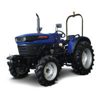
3.6. Engine Coolant Temperature Gauge
The gauge indicates the temperature of the engine
coolant. If the needle enters the red area of the gauge
while the engine is running, decrease the engine RPM
to Idle and investigate the cause.
.
Engine Coolant Temperature Gauge
NOTE : When the key-start switch is turned off, the
gauge needle will assume a random position.
3.7 Engine Oil Pressure Warning Light
The red warning light on the instrument panel
indicates low engine oil pressure and should
extinguish immediately after the engine is started, and
is only operative with the key start switch in the 'ON'
position.
NOTE : If the light comes on while engine is running,
shift the engine RPM to idle immediately and
investigate the cause. The light indicates low oil
pressure and is not an indication of oil level. The
engine oil level must still be checked daily.
3.8 Battery Charging Indicator
The red warning light on the instrument cluster
indicates that the alternator is not charging the battery
and should extinguish when tractor is started.
3.9 Fuel Gauge
The gauge indicates the level of fuel in the tank and is
only operative with the key-start switch in the 'ON'
position.
NOTE : When the key-start switch is turned off the
gauge needle may assume a random position and
may indicates a fuel level greater than the true level.
Always check the fuel level with the key-start switch
on.
1
1
Figure-18
1. Speed Meter
Figure-20
1. Fuel Gauge
1
Figure-19
CONTROL, INSTRUMENTS AND OPERATION