Setup Tyre
13.6x28 (R1)
14.9x28
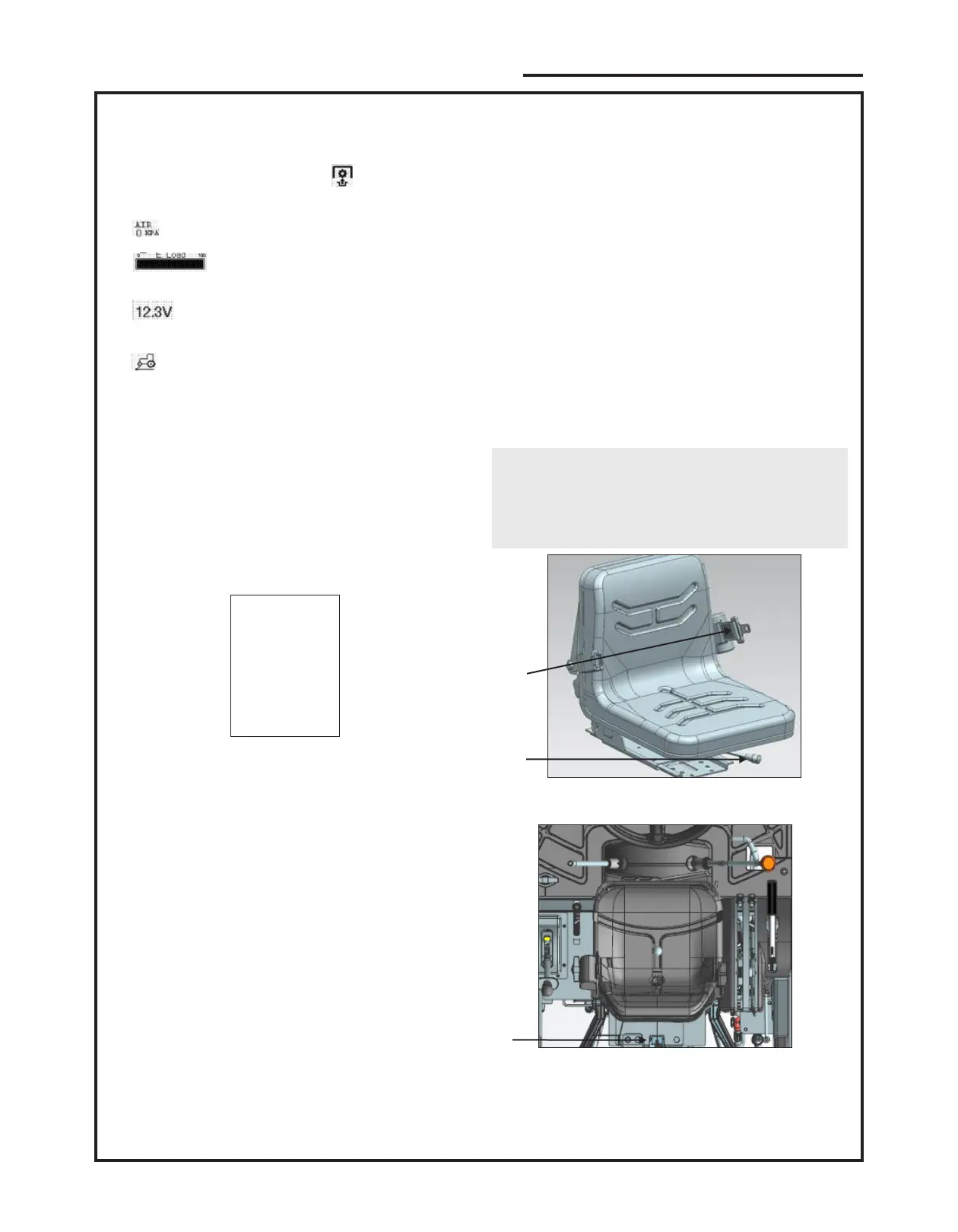
Press Up/down (1,2) button above image will appear
on instrument cluster screen.
1) On top left corner the symbol be glow if PTO
clutch is in ON condition.
2) indicates Air inlet pressure in engine.
3) indicates total RPM in terms of engine
load. 100 means engine is running at full rpm.
4) indicates the battery voltage.It should not be
less than 9 volts.
5) Indication glows if tractor is in 4WD.
3.9.2 Tyre Selection
The instrument gives the possibility to set different tyre
types. Each tyre has its own rolling circumference
used to compute the vehicle speed. To access the
setting screen, you have to press both buttons on the
left at the same time and hold them down for 5
seconds.
The tyre type setup screen is shown, as in the image
below :
The user can scroll the list using the up and down
buttons and select the desired tyre type. To conrm
the selection the user has to press the OK button. After
that the instrument goes to fuel tank selection screen.
To abort the procedure (and keep the previous setting)
the user has to press the menu button on the right. By
pressing menu button, you can skip the current
screen.
At rst access the top line is selected. After the rst
time, the previously set tyre will be selected.
By default (if no tyre is selected, for example at rst
start up) the instrument uses the 13.6x28 tyre.
32
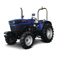
3.11. Operator's Seat
Before operating the tractor, it is important to adjust
the seat to the most comfortable position such that all
the controls are in proper reach and operator should
have proper vision from the tractor.
Driver seat can be adjusted in 2 ways horizontally and
vertically.
3.11.1 Horizontal Adjustment
Horizontal adjustment lever is present below the
operator seat on left hand side. Lift the lever to move
seat forward or backward.
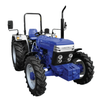
3.11.2. Vertical Adjustment
Use knob (2) to adjust the suspension as per your
weight.
NOTE:
Ÿ Do not use solvents to clean the seat. Use warm
water with a little detergent added.
Ÿ Rms Value of vibration Acceleration is 2.05 m/s at
2
operator’s seat.
Figure-22
1. Horizontal travel adjustment lever
2. Weight adjuster Knob
3. Seat Belt
3
1
2
Figure-23
CONTROL, INSTRUMENTS AND OPERATION