48
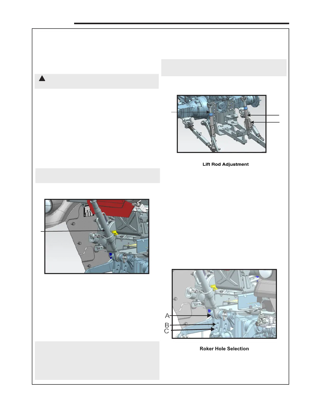
1 . Left Hand Lift Rod 2. Right Hand Leveling Rod
3. Crank Handle for Adjustment
8.1
1
3
2
Figure-56
The length of lift rod can be adjusted by crank handle
(3) provided on both the lift rods as shown in figure 44.
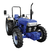
5.13 Hydraulic Lift Rocker
When operating in Draft Control, draft signals are
transmitted via the top link and hydraulic lift rocker to
the control valve within the hydraulic system. The draft
signal transmitted may be varied by adjustment of the
lift rocker connections.
The lift rocker has three holes for attachment of the top
link as shown in figure below.
1
Figure-55
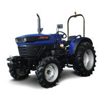
8. 1- Top Link
!
Figure-57
OPERATION
5.10. THREE-POINT LINKAGE AND TRAILED
EQUIPMENT
Before attaching equipment study the following text:
Ÿ Remove the drawbar if mounted or semi- mounted
equipment is attached.
CAUTION: For attaching and detaching the
implement, use position control
Equipments can be attached to your tractor as
follows:
1. Position the lower link hitch point in alignment
with the implements hitch points.
Insert the hitch pins and secure with linch pins.
Always hitch left link first then right link and then
top link, at last.
2. Lengthen or shorten the top link until the
implement mast pin can be inserted through the
mast and top link.
3. For detaching the equipment, reverse the
attaching procedure.
NOTE: Top link should be parallel to the ground in
operating condition.
6.11 TOP LINK
The top link length is adjusted by turning the sleeve.
The locknut must be loosened before the sleeve can
be turned. Most equipment will operate at the correct
depth/height if the top link is set to a nominal 27 in.
(685 mm) measured between the centres of the
attaching pins. When transporting the tractor, hook the
link plate over the lug, on the hydraulic lift rocker. refer
figure 8.
IMPORTANT : While attaching mounted or semi-
mounted equipment to the three-point linkage or
coupling trailed equipment to the drawbar, ensure that
there is adequate clearance between the implement
and the tractor. The clearances in the raised position
should be checked by raising the
A. For hard top soil or low moisture soil
B. For Medium moisture soil or for secondary tillage.
C. For soft moisture soil or during secondary tillage.
implement carefully in position control, Check the
swing clearance by preforming a series of left and
right-hand turns with the tractor and implement
combination.
NOTE : The top link length can be obtained form 590-
840mm. Length or pin at tractor end is 110mm.
5.12 Lift Rod