62
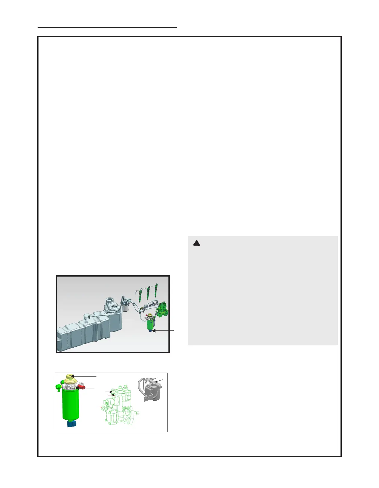
Figure 28. Secondary Fuel Filter
1. Drain Plug
1) Loosen the deflate screw in the main filter.
2) Start priming (using hand primer on filter) until
fuel comes out of the deflate screw without any air
bubble.
3) Tighten the deflate screw.
4) Continue priming till the primer becomes tight for
priming.
5) Crank the engine & ensure successful start. If not
make use of the bleed screw provided on the
pump.
6) Loosen the deflate screw provided on the pump &
then repeat the above steps 2,3,4& 5.
7) Keep the engine in running condition for a certain
time to remove air in low pressure circuit
.8) Similar screw is provided in primary filter and fuel
injection pump for bleeding from respective fuel
circuit.
6.18 Dry Air Cleaner Outer Element
Extract and discard the outer element after removing
the retaining wing nut. Clean the inside of the air
cleaner casing using a damp, lint-free cloth and install
a new outer element.
Remove the outer element and clean.
6.19. Checking Hoses and Clamp
WARNING
To avoid personal injury or death:
• Be sure to stop the engine and remove the key
before checking radiator hose and clamp.
• Allow engine and coolant to cool down sufficiently
before checking.
Check to see if radiator hoses are properly fixed
on every service.
1. If hose clamps are loose or water leaks, tighten
bands securely.
2. Replace hoses and tighten hose clamps securely,
if radiator hoses are swollen, hardened or
cracked.
Replace hoses and hose clamps on every service
if checked and found that hoses are swollen,
hardened or cracked.
6.20 Rear Axle / Transmission Oil Drain
Remove the drain plug and allow the oil to drain
into a suitable container. Replace the plug after
the oil has completely drained. Refill the rear axle
until the oil reaches up to upper mark on dipstick
present on RHS of tractor near the main gear
lever.
1
2
1
Figure 29.
Secondary Fuel Filter
1. Hand Primer 2. Deflate Screw
Figure 30.
Fuel Injection pump
3. Primary Filter Bleed Screw
Fuel Injection pump
Fuel inlet
Fuel return
Bleed Screw
3
LUBRICATION AND MAINTENANCE CHART
Don'ts
Ÿ Lash adjusters must not be kept in upside down
position from the moment of loading on trays up to
the time of assembly on the engine.
Ÿ Engine should not be cranked without oil supply
which allows air to enter HLA which is not
recommended.
Ÿ Avoid all those operation that could make the oil
drain out without the presence of continuous
pressurized oil.
Ÿ Pistons should not to be at T D C during assembly
of overhead to avoid risks of having valves forcing
against pistons, with consequent potential failures
of rocker arms.
Ÿ If the HLA is solid after assembly, engine must not
run for 1.5 hours (time for HLA to reach its working
length) to avoid risk of valve-piston hitting.
Possible failure modes
1. Loss of power/performance
Probable Cause: HLA might be solidified, stop the
engine and check for faulty rocker arm.
2. Loss of Engine rotation
Probable Cause: Pushrod not as per HLA design,
remove rocker arm assembly and check pushrod
cup design.
3. Abnormal tappet noise
Probable cause: Lack of oil supply in HLA,
resulting in sponginess. Check oil flow through
rocker arm, flow should be visible from HLA end.
6.17 Fuel Filter (Bleeding the fuel System)
!