6-7
1
2
3
4
5
6
Appendix
Index List
6-2 Index List
This information is applicable when using the D4RF-T, D4RF-TC4, and D4RF-TD as IO-Link devices.
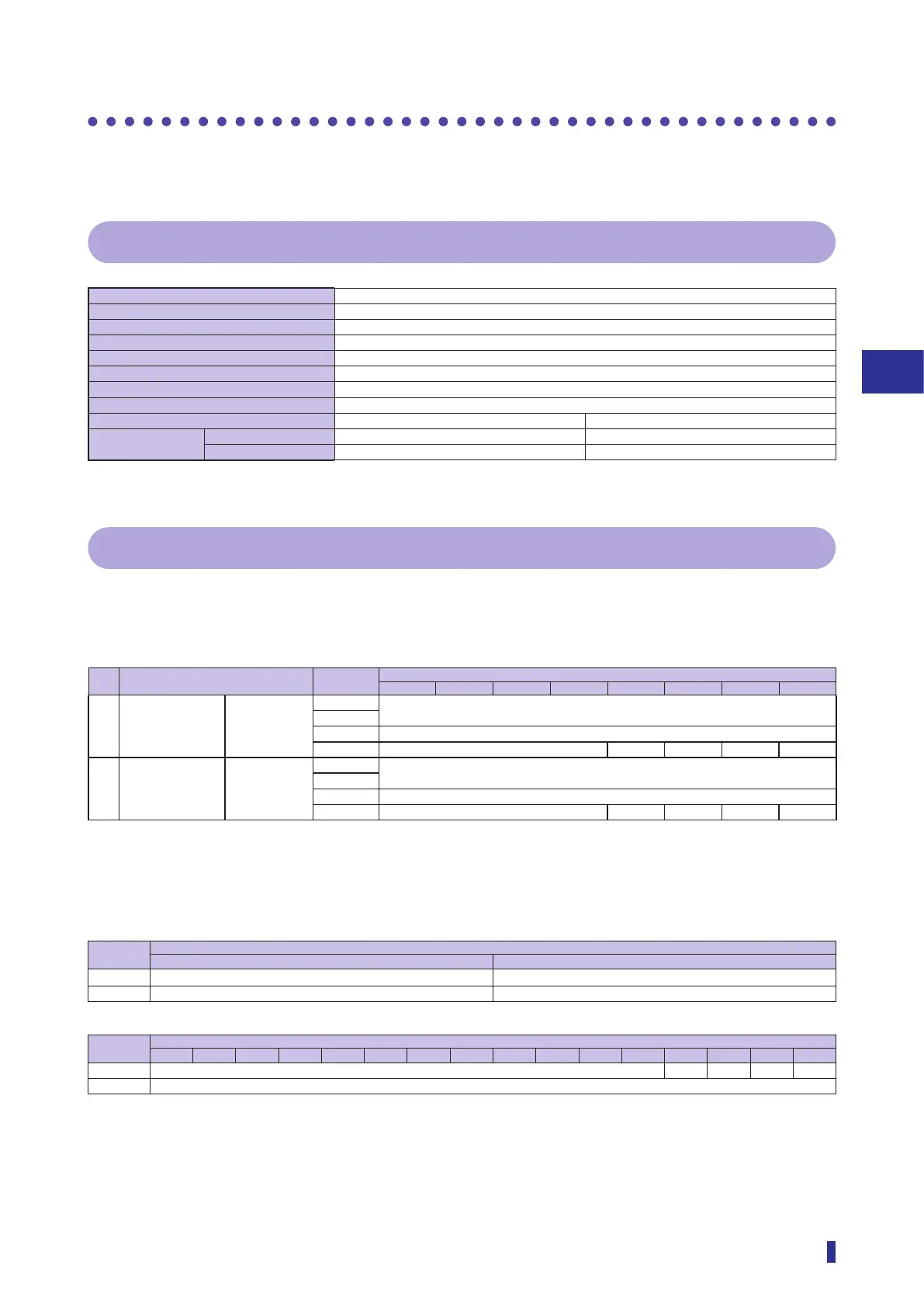
6-2-1 Communication Specifications
Minimum cycle time 0.5 ms
Baud rate COM 3 (230.4 kbps)
M-Sequence code in Pre-operate mode 0
M-Sequence code in Operate mode 4
ISDU support Yes
IO-Link revision 1.1
Number of process input data bytes 4 bytes
Number of process output data bytes 0 bytes
Vender ID DEC: 1076 HEX: 0434
Device ID
(20529) DEC: 65546 HEX: 1000A
(20530, 20531) DEC: 65545 HEX: 10009
6-2-2 Process Data Format
With the D4RF series, the content of process input data transmitted via IO-Link communication can be
selected from the following two formats.
• The format of process input data can be switched by using Index 120.
# Description Byte No.
Bit
7 6 5 4 3 2 1 0
1 When value of
Index 120 is
0x00
* Default setting
Receiving
light level and
output
n+0 Receiving light level
(no units)
n+1
n+2 Reserved
n+3 Reserved Qint. 2 Qint. 1 QL 2 QL 1
2 When value of
Index 120 is
0x12
Counter value
and output
n+0 Counter value
n+1
n+2 Reserved
n+3 Reserved Qint. 2 Qint. 1 QL 2 QL 1
Word Assignment
Example: When using the IO-Link master of OPTEX FA (default setting: little endian)
Word
No.
Byte
Higher order byte Lower order byte
N+0 Process data n+2 Process data n+3
N+1 Process data n+0 Process data n+1
Word
No.
Bit
15 14 13 12 11 10 9 8 7 6 5 4 3 2 1 0
N+0 Reserved Qint. 2 Qint. 1 QL 2 QL 1
N+1 Receiving light level (no units)