2-5
1
2
Installation and Connection
Wiring the Fiber Amplier
2-2 Wiring the Fiber Amplifier
CAUTION
• Be sure to turn off the power before connecting/disconnecting connectors or wiring.
• Cut lead wires that are not used, wrap them individually with insulating tape, and do not allow them to come into
contact with other terminals.
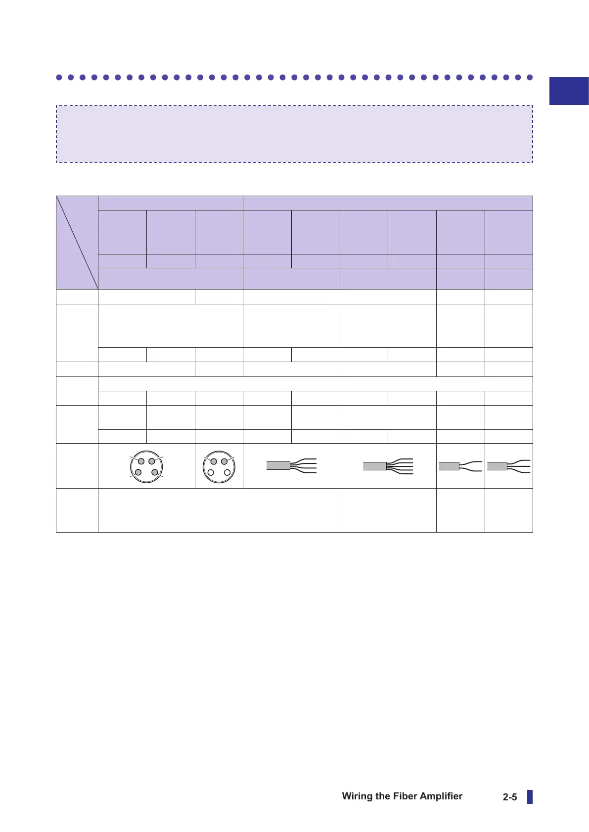
Model
Connection,
etc.
Connector models Cable models
Stand-
alone unit
Inter-
connection
main unit
Inter-
connection
expansion
unit
Stand-
alone unit
Inter-
connection
main unit
Stand-
alone unit
Inter-
connection
main unit
Inter-
connection
expansion
unit
Inter-
connection
expansion
unit
D4RF-TC4 D4RF-TMC4 D4RF-TSC4 D4RF-T D4RF-TM D4RF-TD D4RF-TDM D4RF-TS D4RF-TDS
M8, 4-pin 4 wires 5 wires 2 wires 3 wires
Brown ①
+V — +V — —
White ②
External input/control output 2 External input/control
output 2
External input External
input/
control
output 2
External
input
(IO-Link)
DI/DO switch
— —
DI/DO switch
— DI — — —
Blue ③
0 V — 0 V 0 V — —
Black ④
Control output 1
(IO-Link) C/Q — — C/Q — C/Q — — —
Gray — — — — — Control output 2 — Control
output 2
(IO-Link) — — — — — DO — — —
Connector/
cable
Reference
I/O circuit
diagram
1-output and 1-switchable-output/input models 2-outputs and 1-input
models
1-output and
1-switchable-
output/input
models
2-outputs
and 1-input
models


 To Next Page