2-6
Wiring the Fiber Amplier
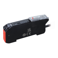
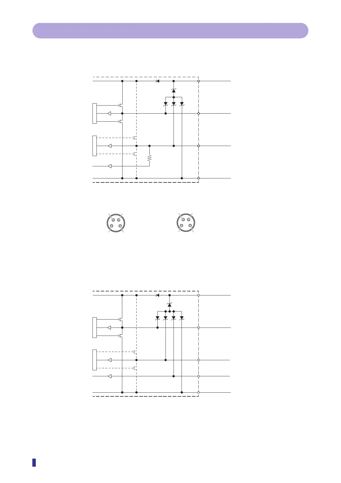
2-2-1 I/O Circuit Diagrams in IO-Link Mode
The circuit diagram by I/O model is shown below.
1-Output and 1-Switchable-Output/Input Models
Black
➃
White
➁
Blue
➂
L+
C/Q
DI/DO
M
➀
L+
➃
C/Q
➁
DI
M8 connector pin layout
➂
M
1-output + 1-input setting
2-output setting
➀
L+
➃
C/Q
➁
DO
➂
M
2-Output and 1-Input Models
Black
Gray
White
Blue
L+
C/Q
DI
DO
M